
Multilayered environmental barrier coating and related articles and methods

Inactive Publication Date: 2006-07-13
GENERAL ELECTRIC CO
View PDF11 Cites 46 Cited by
  • Summary
  • Abstract
  • Description
  • Claims
  • Application Information

AI Technical Summary

Benefits of technology

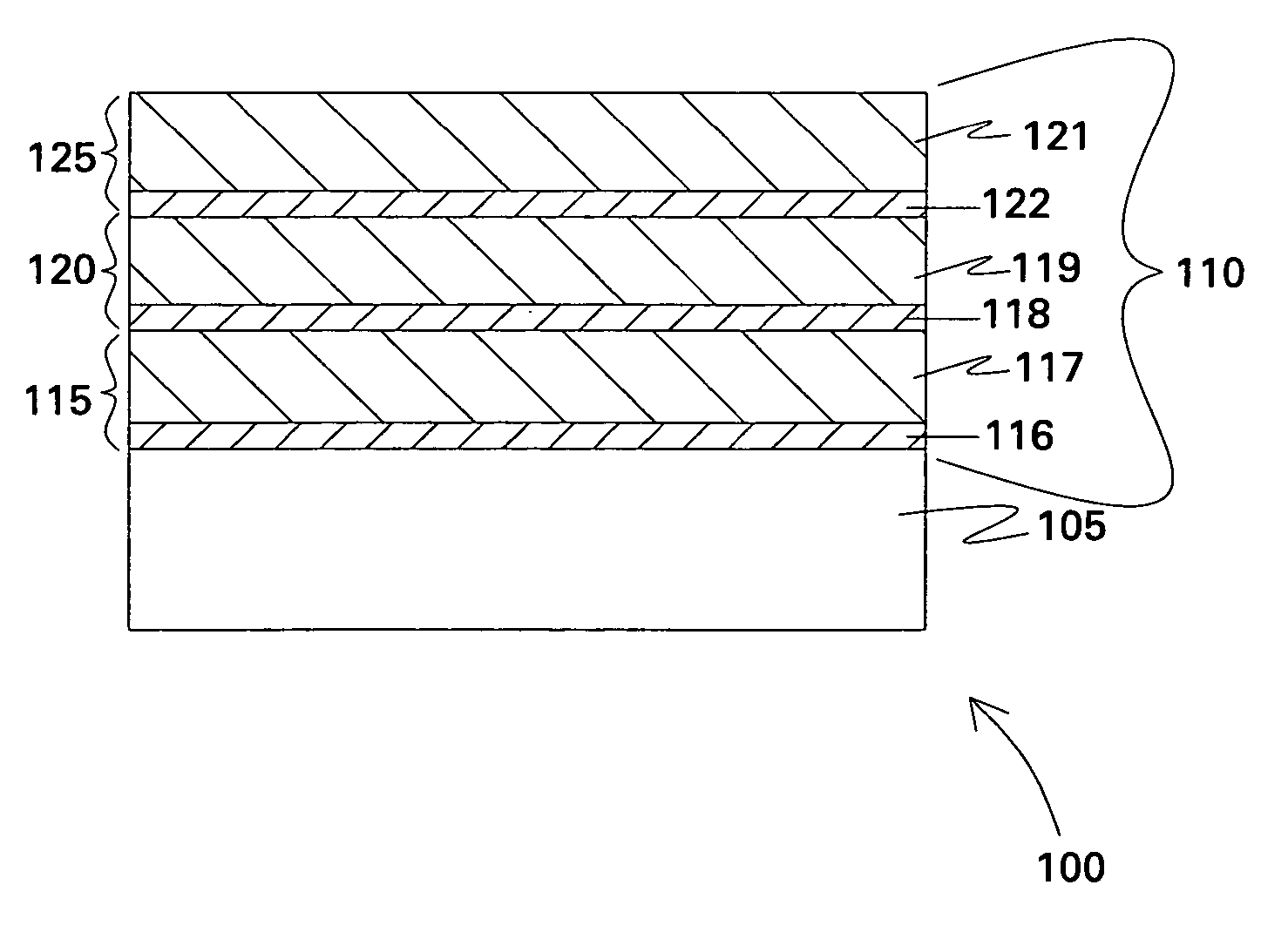
[0011] Embodiments of the present invention introduce redundancy to enhance the robustness of an EBC system. Multiple protective coating units are disposed over a substrate so that, unlike conventional systems described above, failure of one of the coating units will be far less likely to subject the substrate to direct risk of exposure to the environment. Failure of an outer coating unit merely exposes a pristine protective coating unit, rather than the substrate or a less protective coating layer. In this way, embodiments of the present invention drastically reduce reliance on the performance of one particular coating layer, promoting a more robust and reliable system.

Problems solved by technology

However, the environments characteristic of these applications often contain water vapor, which at high temperatures is known to cause significant surface recession and mass loss in silicon-bearing materials.
The water vapor reacts with the structural material at high temperatures to form volatile silicon-containing species, often resulting in unacceptably high recession rates.
However, cracking, spalling, volatilization, and other mechanisms operating on localized areas of the EBC top layer expose the underlying material—a silicon bond coat, for instance—to the environment, leading to rapid oxidation and volatilization.
Perforation of the substrate material can lead to catastrophic failure of the system, as parts that were not designed for high temperature service suddenly become directly exposed to a high temperature environment.

Method used


Image

  • Multilayered environmental barrier coating and related articles and methods
  • Multilayered environmental barrier coating and related articles and methods
  • Multilayered environmental barrier coating and related articles and methods

Examples


example

[0023] Without further elaboration, it is believed that one skilled in the art can, using the description herein, utilize the present invention to its fullest extent. The following example is included to provide additional guidance to those skilled in the art in practicing the claimed invention. The example provided is merely representative of the work that contributes to the teaching of the present application. Accordingly, this example is not intended to limit the invention, as defined in the appended claims, in any manner.

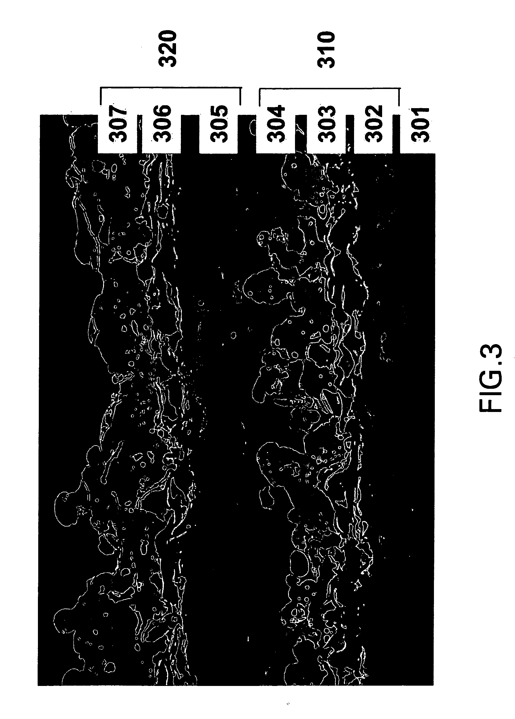
[0024] Referring to FIG. 3, a silicon-bearing substrate 301 was plasma spray-coated with two coating units 310, 320. Each coating unit comprised an oxygen-getter layer 302, 305 of elemental silicon; an additional layer 303, 306 comprising a mixture of BSAS and mullite disposed over the getter layer 302,305; and a barrier layer 304,307 of BSAS disposed over the additional layer 303,306. The total thickness of each unit was approximately 300-500 micrometers. The ...


PUM

PropertyMeasurementUnit
Thicknessaaaaaaaaaa
Thicknessaaaaaaaaaa
Thicknessaaaaaaaaaa

Abstract

An article comprising a substrate and a plurality of coating units disposed over the substrate is provided. Each coating unit comprises an oxygen-getter layer and a barrier layer. Embodiments of the present invention introduce redundancy to enhance the robustness of a coating system. Multiple protective coating units are disposed over a substrate so that failure of one of the coating units will be far less likely to subject the substrate to direct risk of exposure to the environment. Failure of an outer coating unit merely exposes a pristine protective coating unit, rather than the substrate or a less protective coating layer. In this way, embodiments of the present invention drastically reduce reliance on the performance of one particular coating layer, promoting a more robust and reliable system.

Description

BACKGROUND [0001] This invention relates to high-temperature machine components. More particularly, this invention relates to coating systems for protecting machine components from exposure to high-temperature environments. This invention also relates to methods for protecting articles. [0002] Silicon-bearing materials, such as, for example, ceramics, alloys, and intermetallics, offer attractive properties for use in structures designed for service at high temperatures in such applications as gas turbine engines, heat exchangers, and internal combustion engines, for example. However, the environments characteristic of these applications often contain water vapor, which at high temperatures is known to cause significant surface recession and mass loss in silicon-bearing materials. The water vapor reacts with the structural material at high temperatures to form volatile silicon-containing species, often resulting in unacceptably high recession rates. [0003] Environmental barrier coati...

Claims


Application Information

Patent Timeline
IPC IPC(8): B32B17/06B32B13/04B32B9/00B32B15/04
CPCC04B41/009C04B41/52C04B41/89F01D5/282F01D5/284F01D5/288F23M2900/05003F23M2900/05004F23R3/007C04B41/4527C04B41/5096C04B41/5037C04B41/5024C04B41/5032C04B41/522C04B41/5105C04B35/565C04B35/584C04B35/806F05D2240/40C23C28/321C23C28/36F05D2300/21F05D2230/90F05D2300/143C23C28/322C23C28/34C23C28/341C23C28/345C23C28/3455C23C28/42Y10T428/31678
Inventor MESCHTER, PETER JOELLUTHRA, KRISHAN LALSAAK, JENNIFER SUJOHNSON, CURTIS ALAN
Owner GENERAL ELECTRIC CO
Learn More