Fluid control device

a control device and fluid technology, applied in the field of fluid control devices, can solve the problems of inaccurate monitoring of inability to accurately monitor the pressure of patients, and in practical use, so as to reduce the burden on patients, accurately measure the blood pressure of patients, and minimize the effect of pressure load

Inactive Publication Date: 2006-07-13
JMS CO LTD
View PDF5 Cites 32 Cited by
  • Summary
  • Abstract
  • Description
  • Claims
  • Application Information

AI Technical Summary

Benefits of technology

[0007] In view of the above described problems, the present invention relates to a fluid control device which makes it possible to perform more accurate and safer pressure measurement, to measure pressure values accurately reflecting the patient's blood pressure soon after finishing a flushing operation of the infusion line and so on, and to ensure a sufficient flow rate in a relatively low pressure range, and more particularly to a flow control device which can be opened by a predetermined fluid pressure and allows the fluid to flow exactly following the pressure applied to the fluid, in which the fluid flow according to the opening of the device will have substantially no effect on the fluid pressure on the side where the fluid is flown to (exit side), and which ensures a sufficient flow rate in a relatively low pressure range.

Problems solved by technology

However, this type of blood pressure measuring systems had a drawback in that it was rather impossible, in practical use, to accurately monitor the pressure since the pressure in the tube member is affected by the pressure fluctuations of the syringe pump 4 upon administering a drug.
However, the flow control device described in each of the above mentioned patent publication had a problem in that it is difficult for a medical staff to accurately keep track of the blood pressure of a patient because it takes some time until a pressure rise in the line due to a flushing operation is eliminated.
Moreover, the flow control devices disclosed in the above mentioned patent publications are configured such that a seal member having a tubular skirt is placed under a tension so as to come into intimate contact with the outer peripheral surface of the bulged portion, into which periphery the communication path opens, and this configuration makes it difficult to ensure a sufficient flow rate in a relatively low pressure range and to do so even at elevated pressures.
Further, the flow control device used in the X line of FIG. 7 is configured to change the diameter of the path through actuation of the lever, which significantly affects pressure readings of patient's blood pressure, thus raising concerns that there is too much burden on a patient such as infants, and besides it was difficult to obtain accurate pressure readings.

Method used


Image

  • Fluid control device
  • Fluid control device
  • Fluid control device

Examples


embodiment 1

1. Embodiment 1

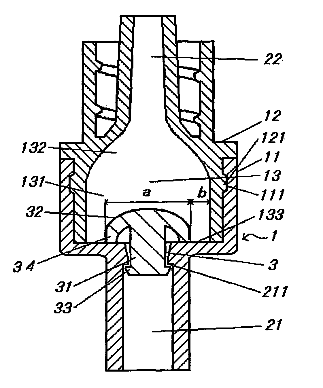
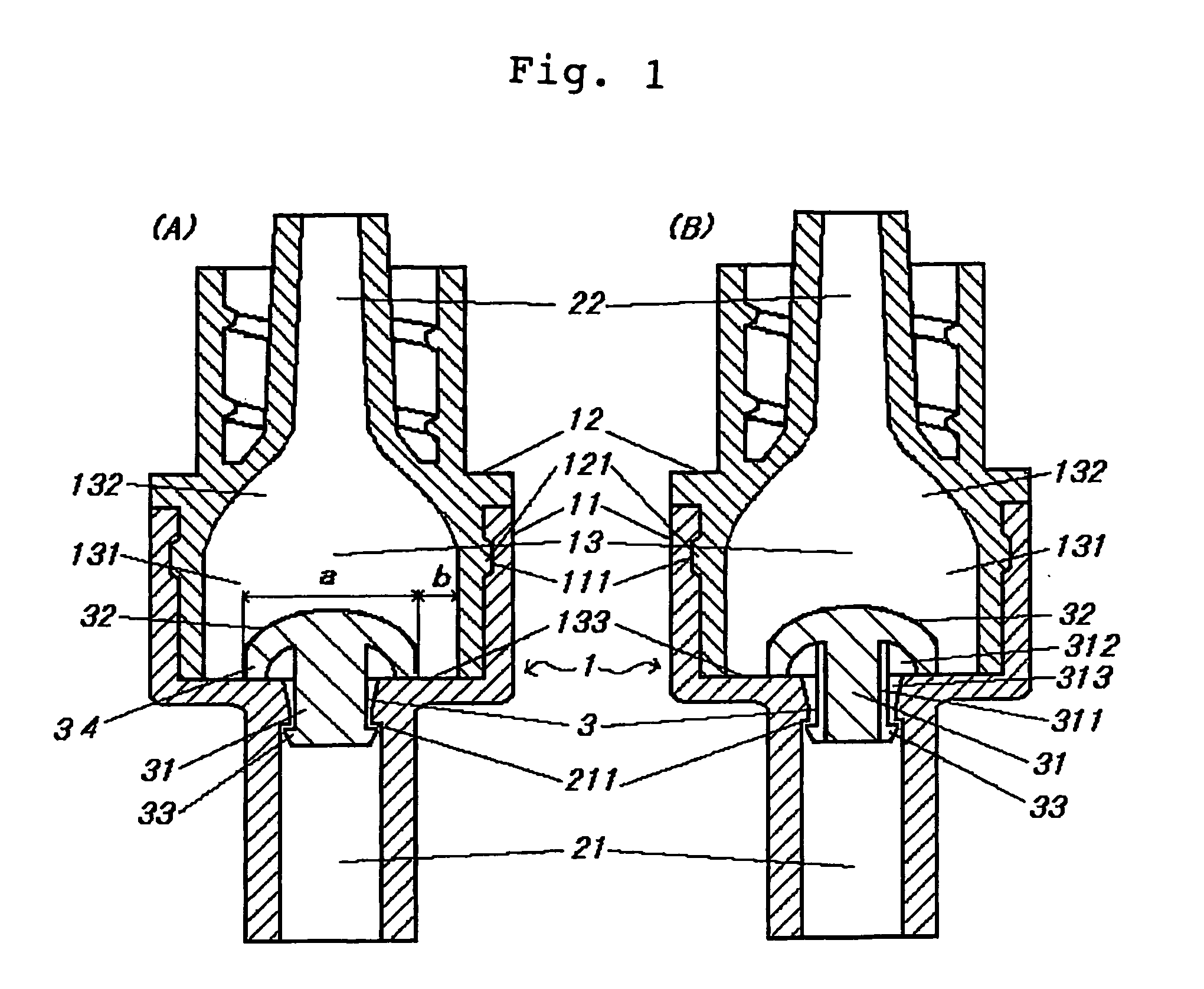
[0037] As shown in FIG. 1, the tube body constituting the first fluid path 21 is bulged at its end to form the first housing portion 11, and the tube body constituting the second fluid path is bulged at its end to form the second housing portion 12. The housing portion 1 is configured by fitting the second housing portion 12 into the first housing portion 11 so as to be enclosed therein, and the material for the first housing portion 11 is polypropylene resin and the material for the second housing portion 12 is polycarbonate resin.

[0038] Further, the first housing portion 11 and the second housing portion 12 are formed respectively with fitting portions 111, 121 having a convex and a concave shapes, and by engaging these fitting portions together, it is made possible to prevent both housing portions from being detached thereby ensuring air tightness and pressure resistance in the fluid control device.

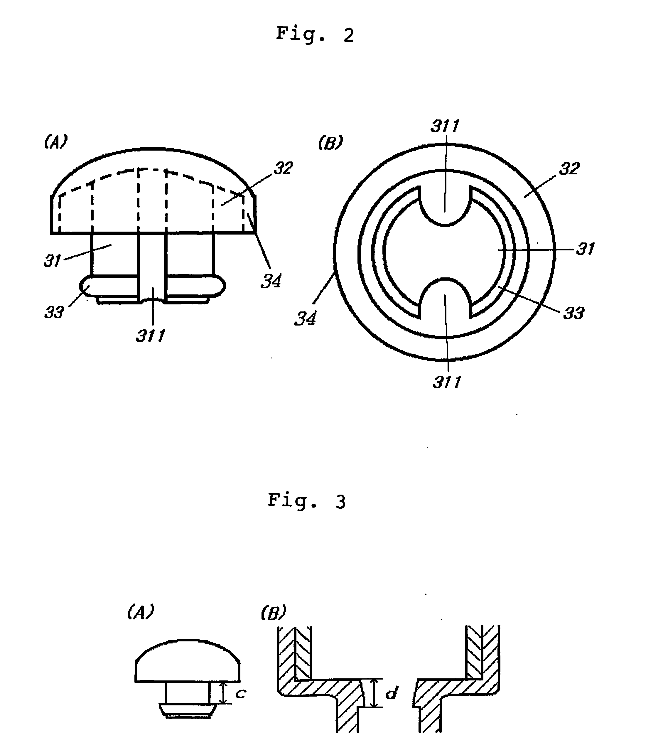
[0039] The body portion 31 of the valve member 3 is formed of a c...

embodiment 2

2. EMBODIMENT 2

[0054]FIG. 4 is a schematic view of a blood pressure measurement system installed with the fluid control device of the present invention and for conducting blood pressure measurement while performing an infusion therapy, in which providing the fluid control device of the present invention in the infusion therapy line as described below makes it is possible: to prevent pressure fluctuations in the line due to the installment of the fluid control device, to accurately detect the pressure of the fluid flowing in the line, to complete a flushing operation in a shorter period of time, and further to readily cope with any alarm setting level of the alarm device provided in the line.

[0055] A patient is administered with a drug, which is delivered from the injector 41 through the driving of the syringe pump 4 into the blood vessel or the like via the tube member 7 and the puncture needle provided at the tip end thereof. At this moment, there is provided a line branched from ...


PUM


Abstract

A fluid control device is characterized in that the device is structured of a hollow first fluid path (21) and second fluid path (22), a housing portion (1) formed between the first fluid path and the second fluid path and having a hollow portion with a cross-sectional area larger than cross-sectional areas of both fluid paths, and a valve member (3) that has a main body (31) and a projection portion (32) that are installed in an opening portion where the first fluid path is connected to the hollow portion and that is formed of an elastic material. The fluid control device enables the circulation of liquid when the pressure of liquid flowing from the first fluid path toward the second fluid path is more than a predetermined level. The fluid control device enables accurate and safe measurement of pressure including blood pressure, and, when flushing operation of an infusion circuit etc. is finished, the device enables speedy lowering of pressure to a value that accurately reflects blood pressure of a patient and enables obtaining of a necessary flow rate in a region where pressure is relatively low.

Description

TECHNICAL FIELD [0001] The present invention relates to a fluid control device for medical uses, particularly a fluid therapy; a valve structure of the fluid control device; and a blood pressure measurement system equipped with the fluid control device. BACKGROUND ART [0002] In a typical medical fluid therapy, a drug is administered into a blood vessel or the like of a patient via an infusion line from a container accommodating a drug, such as an infusion bag and an injector filled with a drug. In such a fluid therapy, there are cases in which the blood pressure of a patient is measured and monitored concurrently with drug administration as shown in FIG. 6. That is, a conventional infusion line consists of an injector 41 filled with a drug, a syringe pump 4 (a drug supplying part) for ejecting the drug from the injector 41, a tube member 7 for transporting the drug, and a puncture needle 9 provided at the end of the tube member and to be inserted into a blood vessel or the like of a...

Claims


Application Information

Patent Timeline
Patent Type & Authority Applications(United States)
IPC IPC(8): A61M5/00A61B5/0215A61M5/14A61M5/168A61M39/24
CPCA61B5/0215A61M5/16881A61M39/24A61M2005/1403A61M2039/242A61M2039/2433A61M2039/2466A61M2039/2473A61M2039/2486A61M2230/30
Inventor HASHIMOTO, SATORUFUJII, RYOJISAWA, KENJI
Owner JMS CO LTD
Why Eureka
Try Eureka