Motor overspeed detection

Active Publication Date: 2006-07-20
BLUE LEAF I P
View PDF6 Cites 6 Cited by
  • Summary
  • Abstract
  • Description
  • Claims
  • Application Information

AI Technical Summary

Benefits of technology

[0018] The method may further include a step of electronically calculating a first of the two alternative motor speeds based upon a signal from a motor speed sensor. The method may further include a step of electronically calculating a second of the two alternative motor speeds based upon signals from an engine speed sensor and a rotor speed sensor. The combine may include a planetary gear set coupling the engine and motor to the rotor and a clutch coupled to and between the engine and the planetary gear set. The step of disengaging the motor may include the step of disengaging the clutch. The at lea

Problems solved by technology

However, in order to increase the amount of crop processed by the combine, the size, weight and power consumption of the rotor are being increased to levels above the tolerances of belt driven technology.
It is difficult to accelerate such a rotor from rest, particularly under certain crop conditions, because accelerating the high-inertia rotor places high stresses on both the belt drive and the clutch used to engage the belt drive.
The stress on the clutch and belt can be severe, resulting in early clutch and belt failure.
Additionally, there are instances in which the combine encounters a “slug” condition in which the operator may determine that the crop is lodged between the rotor and concave.
While the addition of a motor to permit gradual acceleration does reduce damage to a belt, it also adds an additional components—the hydraulic motor—that itself is susceptible to damage under extreme operating conditions.
When a split torque system is subjected to severe and sudden loading, the driving torque

Method used


Image

  • Motor overspeed detection
  • Motor overspeed detection
  • Motor overspeed detection

Examples


Embodiment Construction

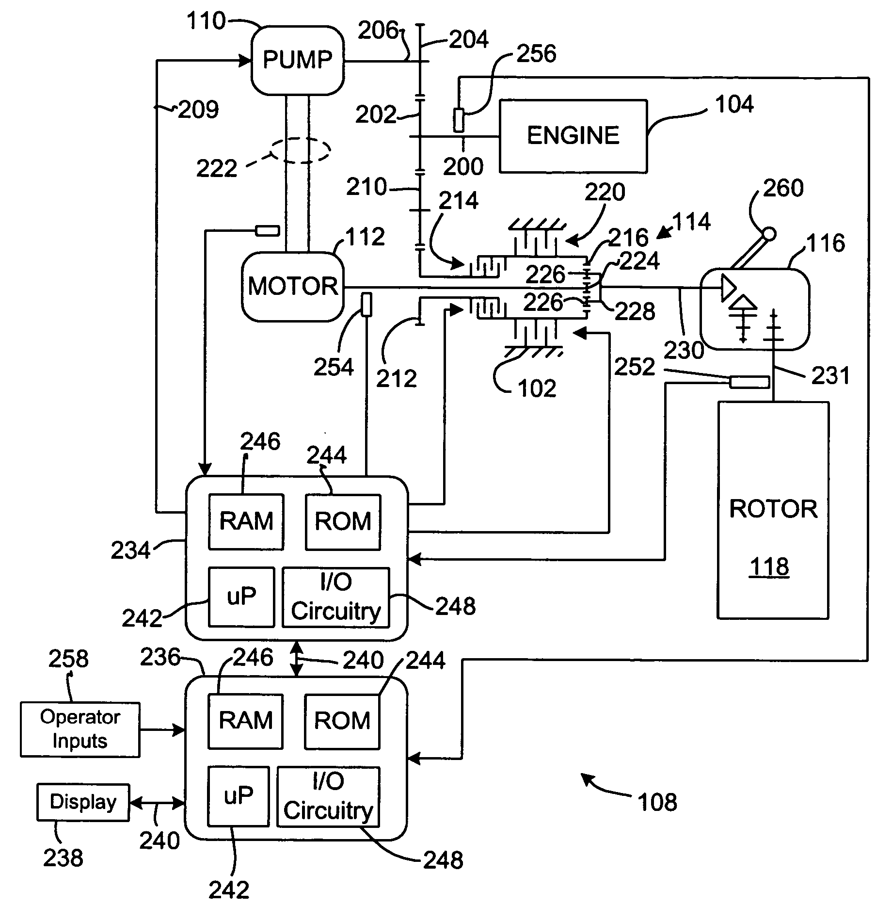
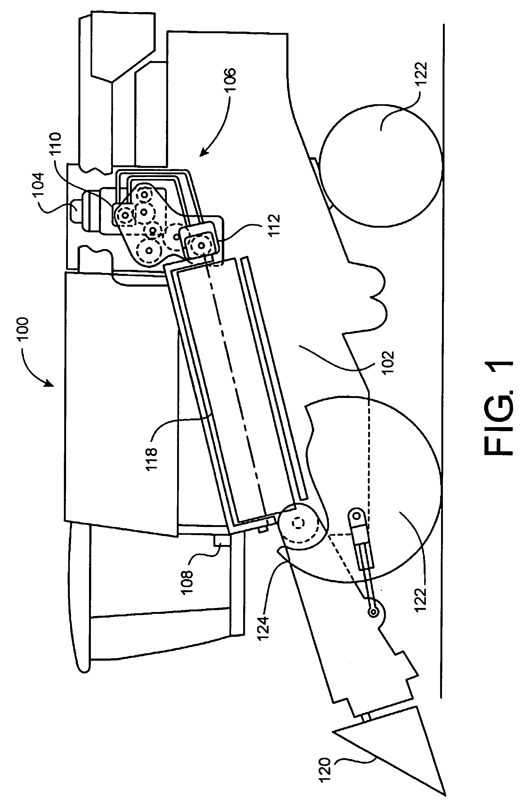
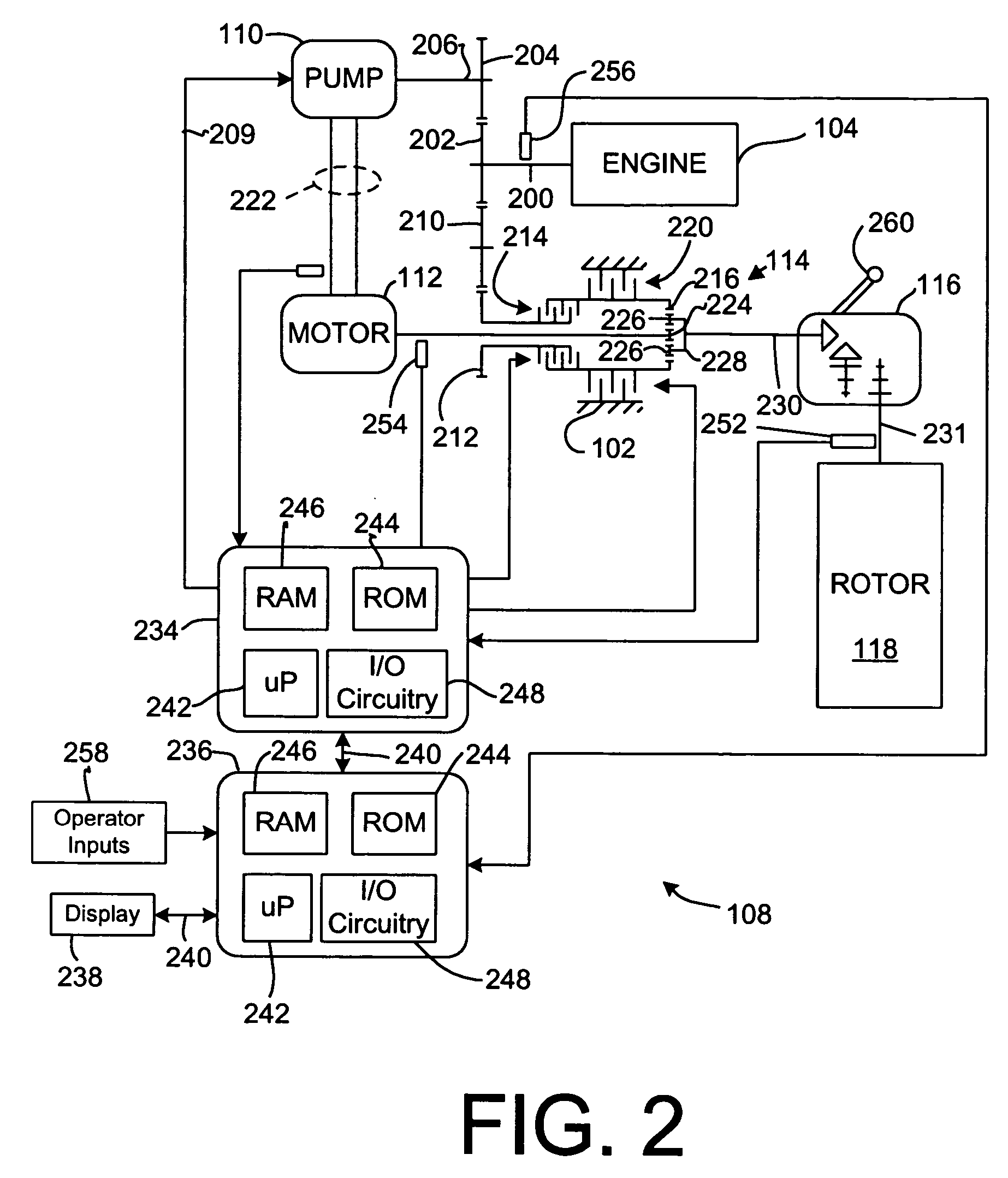
[0025] Referring to FIGS. 1 and 2, a work vehicle is illustrated, here shown as an agricultural combine 100. The work vehicle has a chassis 102 on which an engine 104 is mounted. A drive system 106 is coupled to and driven by engine 104 to rotate rotor 118. An electronic control system 108 is coupled to the engine and the drive system to monitor various sensors, to control the engine and to control the drive system.

[0026] The engine 104 is preferably an internal combustion engine, such as a multi-cylinder gasoline or diesel engine.

[0027] The drive system 106 includes a hydraulic pump 110 that is coupled to and driven by the engine, a hydraulic motor 112 that is fluidly coupled to and driven by pump 110, gear trains coupling engine 104 to the pump, engine 104 to a planetary gear arrangement, the planetary gear arrangement itself, and a gearbox driven by the planetary gear arrangement that, in turn, drives the combine rotor 118.

[0028] Rotor 118 rotates with respect to chassis 102 a...


PUM


Abstract

A motor control system of a combine having a rotor that is simultaneously driven by an engine and a hydraulic motor is configured to determine at overspeed condition of the motor and to disengage the motor from the engine when the overspeed condition exists.

Description

CROSS-REFERENCE TO RELATED APPLICATIONS [0001] The present application is related to U.S. patent application Ser. No. 10 / 166,951, now issued as U.S. Pat. No. 6,695,693; to U.S. patent application Ser. No. 10 / 166,916, now issued as U.S. Pat. No. 6,702,666; to co-pending U.S. patent application Ser. No. 10 / 167,310 from which this application claims priority as a continuation-in-part application, and to co-pending U.S. patent application Ser. No. 10 / 199,681 from which this application also claims priority as a continuation-in-part application.FIELD OF THE INVENTION [0002] The invention relates to agricultural combines and systems for controlling their operation. More particularly, it relates to control systems for controlling the speed of hydraulic motors that drive combine rotors. Even more particularly, it relates to control systems that prevent the overspeeding of hydraulic motors that drive combine rotors. BACKGROUND OF THE INVENTION [0003] Agricultural combines or “combine harvest...

Claims


Application Information

Patent Timeline
IPC IPC(8): F16D31/02
CPCA01D41/1276F16D2500/10412F16D2500/1087F16D2500/111F16D2500/30406F16D2500/3067F16D2500/5046F16D2500/51F16D2500/70424F16D2500/70426
Inventor BROME, JOHN G.HO, YUN-REN
Owner BLUE LEAF I P
Why Eureka
Try Eureka