Image heating apparatus and heater for use in this apparatus

a heating apparatus and heater technology, applied in the field of image heating apparatus, can solve the problems of small electric power consumption during a standby time when it waits for the printing command, and damage to the holder holding the heater and the pressure roller in some cases, so as to suppress the excessive temperature rise of the non-sheet passing area of the heater

Inactive Publication Date: 2006-07-20
CANON KK
View PDF10 Cites 31 Cited by
  • Summary
  • Abstract
  • Description
  • Claims
  • Application Information

AI Technical Summary

Benefits of technology

[0015] According to the present invention, the excessive temperature rise of the non-sheet passing area of the heater can be suppressed.

Problems solved by technology

Also, the fixing device of this type has the merit that electric power consumption during a standby time when it waits for the printing command is small.
Now, it is known that when recording materials of a small size are continuously printed at the same print intervals as for recording materials of a large size by a printer mounting thereon a fixing device using a flexible member, that a temperature of an area of a heater on which the recording materials do not pass (non-sheet passing area) excessively rises.
When the temperature of the non-sheet passing area of the heater excessively rises, a holder holding the heater and a pressure roller may in some cases be damaged by heat.
Accordingly, these patent publications do not suppose an image heating apparatus having a flexible member of which one side contacts with a recording material and the other side contacts with a heater, i.e., an image heating apparatus in which the excessive temperature rise of the non-sheet passing area of a heater occurs.

Method used


Image

  • Image heating apparatus and heater for use in this apparatus
  • Image heating apparatus and heater for use in this apparatus
  • Image heating apparatus and heater for use in this apparatus

Examples


embodiment 1

(1) Example of an Image Forming Apparatus

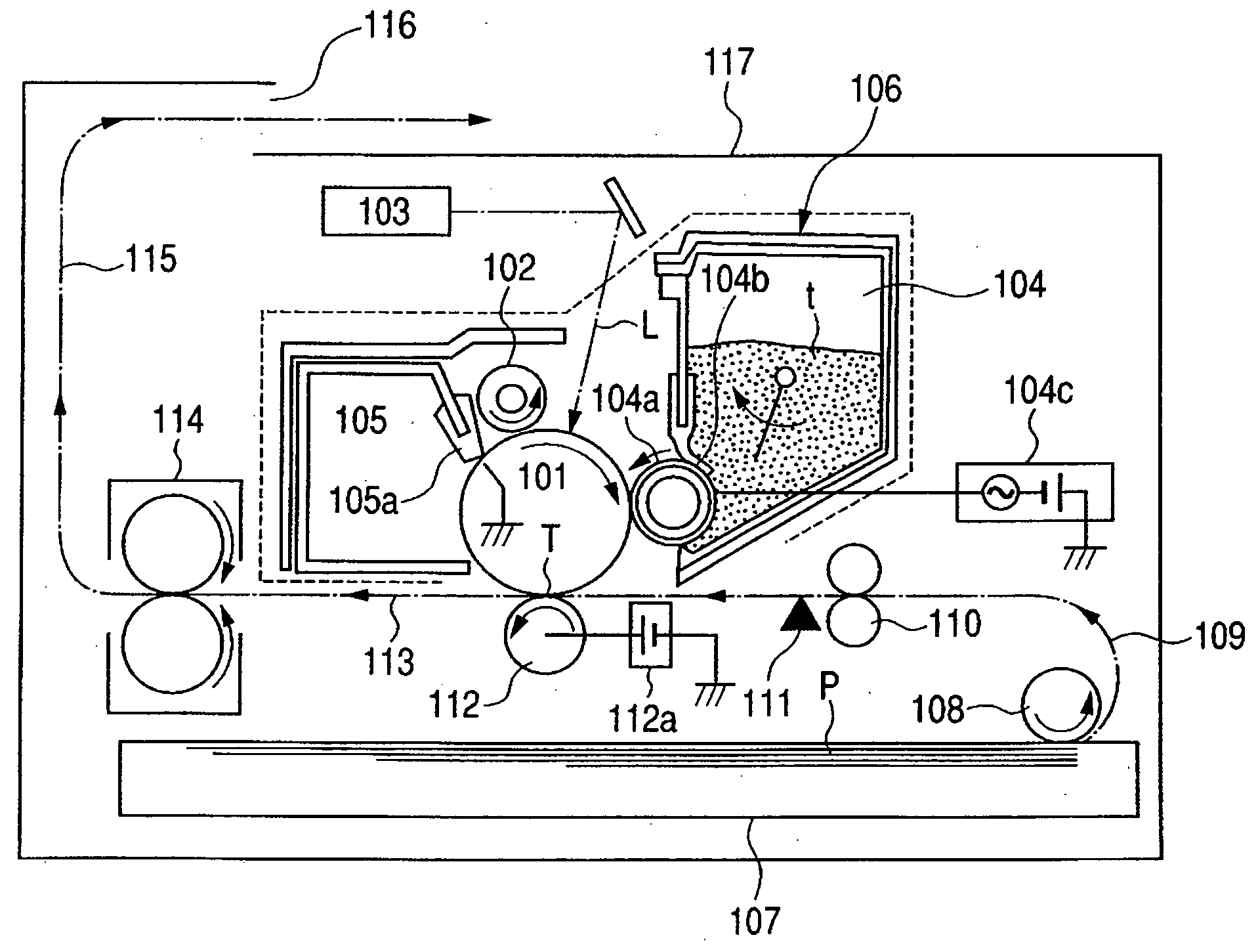
[0030]FIG. 1 schematically shows the construction of an image forming apparatus mounting the image heating apparatus of the present invention thereon. This image forming apparatus is a laser beam printer using a transfer type electrophotographic process.

[0031] The reference numeral 101 designates a drum-shaped electrophotographic photosensitive member (hereinafter referred to as the photosensitive drum) as an image bearing member. It is, for example, an organic photosensitive drum comprising an electrically conductive drum base of aluminum or the like and a photosensitive layer of an organic photoconductor or the like formed on the outer peripheral surface thereof.

[0032] The reference numeral 102 denotes a charging roller as charging means. The surface of the photosensitive drum is uniformly charged to a predetermined polarity and predetermined potential by this charging roller 102. In the printer in the present embodiment, it is uniforml...

example 1

HEATER EXAMPLE 1

[0086] In this example of the heater (carbon heat generating member), chlorinated vinyl chloride resin, graphite powder and boron nitride were dispersed and kneaded, and the mixture was molded into a bar shape by an extrusion molding machine, whereafter it was heat treated at 1500° C. in a vacuum (0.01 Pa or less). Thereby, there was obtained a base material having specific resistance of 30.1×10⁻³ Ω·cm in a room temperature environment (20° C.). This base material was worked into a shape of length 250 mm×width 5 mm×thickness 0.5 mm, having a total resistance value of 30.1 Ω.

[0087] Now, the load deformation temperature of a liquid crystal polymer used for the heater support member (the stay 1 in the present embodiment) is in the vicinity of 300° C. Also, the fusing point of fluorine resin such as PFA or PTFE used as the material of the surface layer of the film (flexible member) frictionally contacting with the heater, and the surface layer of the pressure roller con...

example 2

HEATER EXAMPLE 2

[0093] In the same manner as in Embodiment 1 with the exception that the heat treating temperature in the vacuum was 1650° C., there was obtained a base material having specific resistance of 10×10 Ω·cm in a room temperature environment (20° C.). This base material was worked into a shape of length 250 mm×width 5 mm thickness 0.5 mm, having a total resistance value of 10 Ω. Also, as the resistance temperature characteristic of the present Heater Example 2 in FIG. 10 shows, the rate of change in resistance of this heater is always negative in the temperature area of the room temperature to 300° C.

[0094] Incidentally, the rate of change in resistance of the present Heater Example 2 was found to be [(resistance value at 300° C.=9.15Ω) / (resistance value of room temperature environment=10Ω)−1]≈−0.085.

[0095] That is, it can be seen that Heater Example 2 has the NTC characteristic within a temperature range of 20° C. to 300° C.


PUM


Abstract

An image heating apparatus which can suppress the excessive temperature rise of the non-sheet passing area of a heater. In an image heating apparatus having a heater generating heat by electrical energization, a flexible member moved while contacting with the heater, and a backup member cooperating with the heater with the flexible member interposed therebetween to form a nip portion, and for heating a recording material bearing an image thereon while nipping and conveying the recording material between the flexible member and the backup member, the heater is constructed by heat-treating a raw material containing an organic matter in an atmosphere wherein carbon is hardly oxidized to thereby carbonize the organic matter.

Description

[0001] This application is a continuation of International Application No. PCT / JP2005 / 020762, filed Nov. 7, 2005, which claims the benefit of Japanese Patent Application No. 2004-323638, filed Nov. 8, 2004 and Japanese Patent Application No. 2005-319529, filed Nov. 2, 2005.BACKGROUND OF THE INVENTION [0002] 1. Field of the Invention [0003] The invention relates to an image heating apparatus suitable for use as an image fixing apparatus mounted on an image forming apparatus such as, for example, an electrophotographic copying machine or an electrophotographic printer, and a heater for use in this apparatus. The present invention relates particularly to an image heating apparatus having a heater generating heat by electrical energization, a flexible member moved while contacting with the heater, and a backup member cooperating with the heater with the flexible member interposed therebetween to form a nip portion, and for heating a recording material bearing an image thereon while nipp...

Claims


Application Information

Patent Timeline
Patent Type & Authority Applications(United States)
IPC IPC(8): H05B3/00H05B1/00
CPCG03G15/2057G03G2215/2035
Inventor OMATA, MASAHITONAKAZONO, YUSUKETOMOYUKI, YOJITANIGUCHI, SATORUKOSUZU, TAKESHI
Owner CANON KK
Why Eureka
Try Eureka