This helps you quickly interpret patents by identifying the three key elements:
Problems solved by technology
Method used
Benefits of technology
Benefits of technology
[0014] Further, there has been a problem that it takes a long time (a long recovery time) to recover the previous temperature of the heating face and productivity reduces in the case a semiconductor wafer is placed on the metal plate and the temperature of the heating face of the metal plate abruptly drops.
[0100] In addition to that, use of the same material for the metal plates and the presser can prevent deformation of the metal plates attributed to the difference of the thermal expansion coefficients between them.
Problems solved by technology
However, metal heaters with such structures have the following problems.
If such warping, sagging and the like occurs in the metal plates, a semiconductor wafer placed on the metal plates cannot be heated evenly, so that a dispersion of temperature or a damage in the semiconductor wafer is generated in some cases.
However, if the metal plates are made thick, the heat capacity of the metal plates is increased, and in the case of heating or cooling an object to be heated, the temperature of the heating faces of the metal plates cannot promptly follow the change of the voltage or the electric current applied to the heating elements, and there has been a problem that temperature control becomes difficult.
Method used
Image
Click on the blue label to locate the original text in one second.
Reading with bidirectional positioning of images and text.
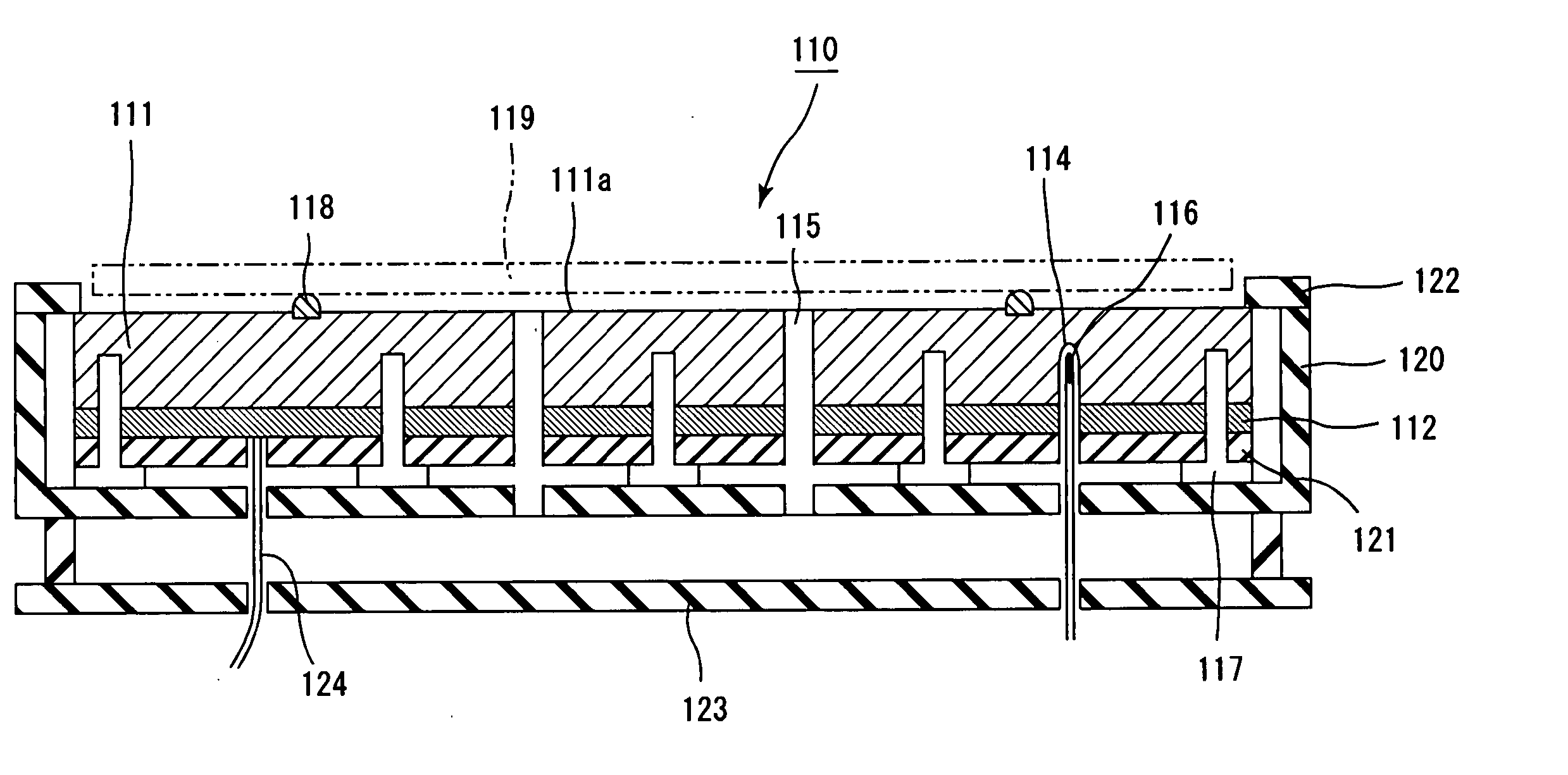
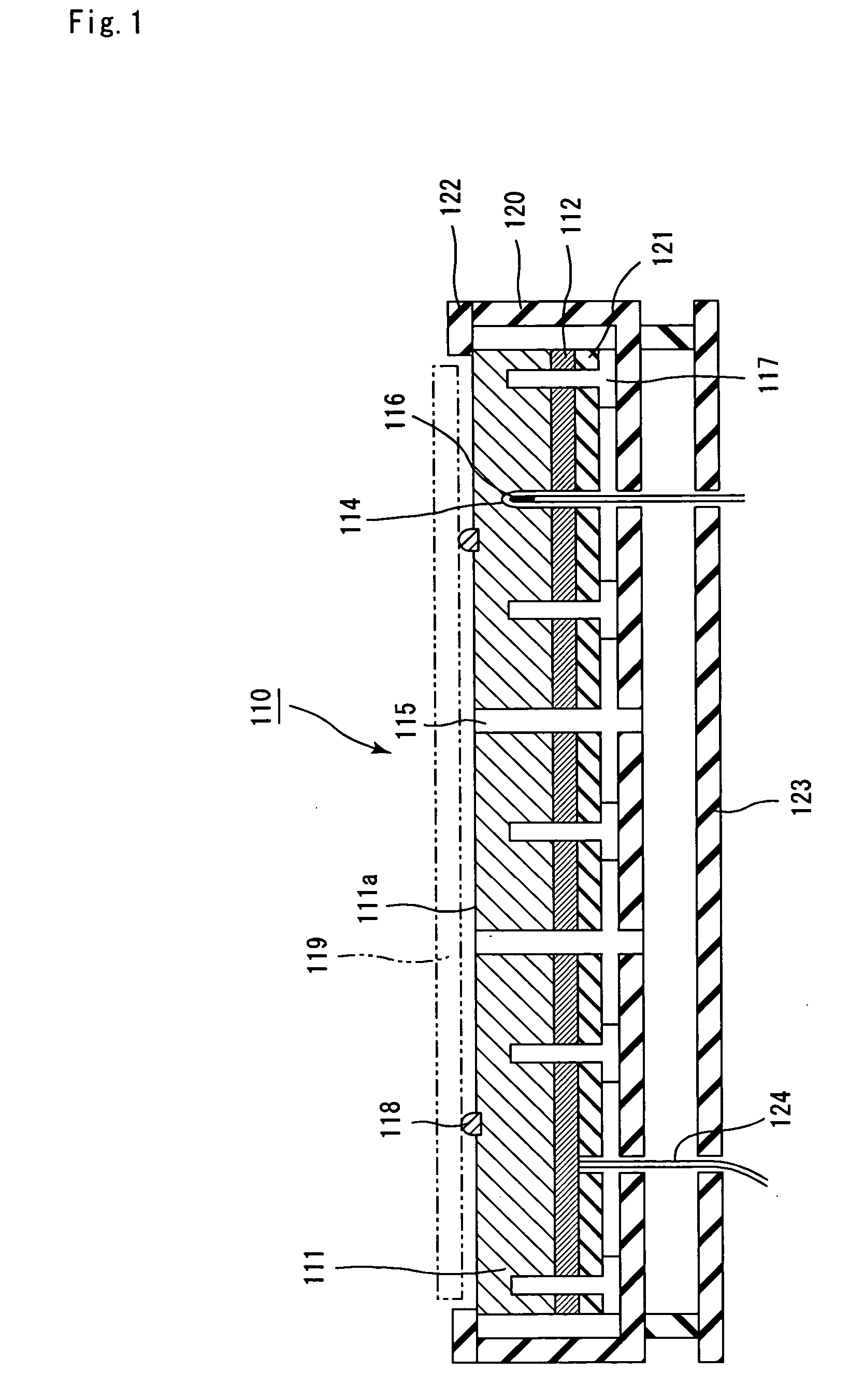
[0249] (1) Plates comprising an aluminum-copperalloy (A 2219 (JIS-H4000)) were formed into a disc shape by outer-diametermachining using an NC lathe (manufactured by Washino Machinery Co., Ltd.). The disc plates were further subjected to the end face machining, front face machining and rear face machining to produce a disc plate for the metal plate and a disc plate for the heater fixation plate.
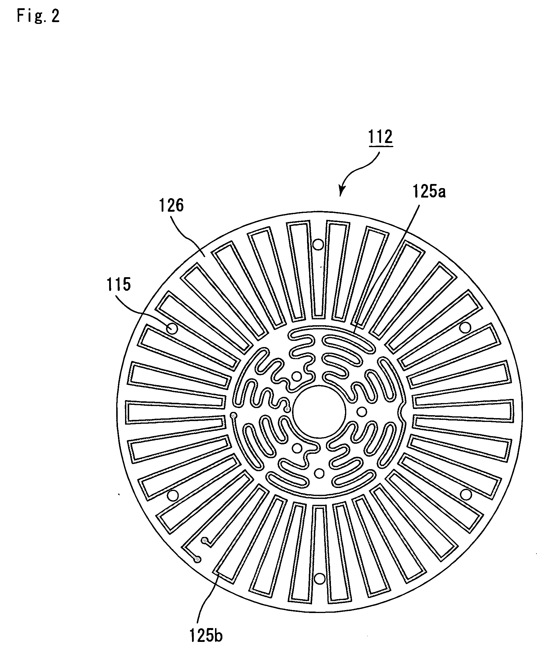
[0250] Next, using a machining center (manufactured by Hitachi Seiki Co., Ltd.), parts to be the through holes 115 to insert lifter pins for supporting the semiconductor wafer 119, concave portions for installing the supporting pins 118, and a part to be the bottomed hole 114 for embedding the temperature measuring element 116 were formed in these disc plates. Further, after the bottomed hole or through holes were formed at prescribed positions in the same manner, screw grooves were formed in the bottomed hole or through holes to form screw...
[0262] A metal heater was produced in the same manner as Example 1, except that the thickness of the metal plate 111 was 5 mm and the thickness of the heater fixation plate 121 was 20 mm.
[0263] Incidentally, with respect to the above metal heater, the outer rim of the region where the heating element was formed existed at a position of 15% of the diameter of the metal plate 111 from the outer circumference of the metal plate 111.
[0264] (1) After the upper metal plate 131 and the lower metal plate 141 were produced in the same manner as described in (1) and (2) in Example 1, the upper metal plate 131 and the lower metal plate 141 were subjected to the alumite treatment in the same manner as described in (3) in Example 1.
[0265] Incidentally, the upper metal plate 131 was produced so as to have a thickness of 2 mm and a diameter of 330 mm, and the lower metal plate 141 was produced so as to have a thickness of 20 mm and a diameter of 330 mm.
[0266] (2) Next, in the same manner as described in (4) to (7) in Example 1, the upper metal plate 131 and the lower metal plate 141 were united with the heater 132 and then installed in the supporting case 140 to obtain the metal heater 130.
[0267] Incidentally, with respect to the constitution of the metal heater of this Example, no screw hole was formed in the upper metal plate 131, and the screw heads of the metal plate fixin...
PUM
Abstract
The object of the present invention is to provide a metal heater capable of quickly heating a semiconductorwafer and the like with slight unevenness of temperature at the time of heating, and causing no warping or sagging in the metal plate employed therein. The metal heater of the present invention comprises a metal plate and a heating element, wherein the metal plate has a thickness of 50 mm or less and a surface flatness of 50 μm or less, and an outer rim of a region where the heating element is formed is at a position within 25% of the diameter of the metal plate from an outer circumference of the metal plate.
Description
TECHNICAL FIELD [0001] The present invention relates to a metal heater to be employed mainly in semiconductor industries and optical industries. BACKGROUND ART [0002] With respect to an etching device, and a semiconductor producing / examining device including a chemical vapor deposition device or the like, metal heaters having substrates of a metal material such as stainless steel have been used. [0003]FIG. 4 is a cross section view schematically showing the situation a siliconwafer is placed on a metal heater with a conventionally employed constitution. [0004] In a metal heater 50, a heater 52 is installed on the bottom face of a disc-shaped metal plate 51 through an intermediate plate 61 comprising a material such as copper excellent in thermal conductivity, and the metal plate 51, the heater 52, and the intermediate plate 61 are fixed in a supporting case 60 by metal plate fixing screws 57. [0005] The heater 52 is connected with a conductive wire 64, and the conductive wire 64 is...
Claims
Application Information
Patent Timeline
Application Date:The date an application was filed.
Publication Date:The date a patent or application was officially published.
First Publication Date:The earliest publication date of a patent with the same application number.
Issue Date:Publication date of the patent grant document.
PCT Entry Date:The Entry date of PCT National Phase.
Estimated Expiry Date:The statutory expiry date of a patent right according to the Patent Law, and it is the longest term of protection that the patent right can achieve without the termination of the patent right due to other reasons(Term extension factor has been taken into account ).
Invalid Date:Actual expiry date is based on effective date or publication date of legal transaction data of invalid patent.

