
Systems and methods for optical pumping using depolarizing filters

Inactive Publication Date: 2006-07-20
SANMINA-SCI CORPORATION
View PDF11 Cites 2 Cited by
  • Summary
  • Abstract
  • Description
  • Claims
  • Application Information

AI Technical Summary

Benefits of technology

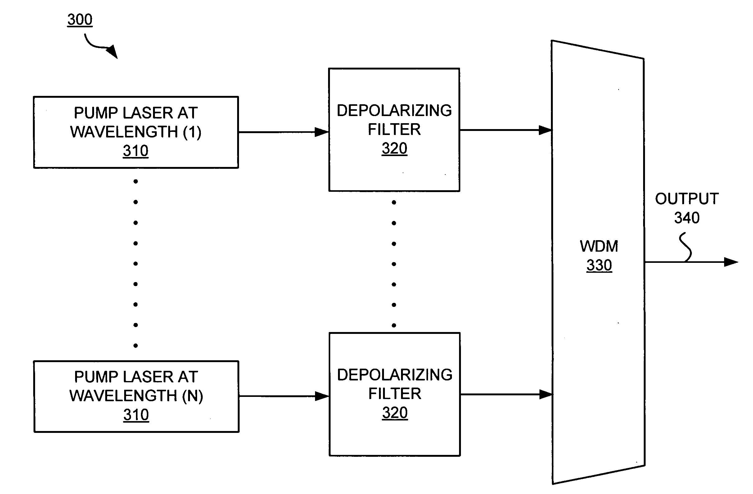
[0015] These systems and methods advantageously provide at least one optical pump signal with the required energy spread across multiple polarizations with fewer optical pump lasers. The reduction of optical pump lasers may eliminate the need to balance or adjust the power and polarization of each optical pump laser. Further, by reducing the number of optical pump lasers, the rate of component failure also reduces. As a result, these systems and methods are more reliable and may reduce maintenance costs. These systems and methods may also reduce the size and weight of the optical pumping system. Moreover, as a result of the reduction of optical pump lasers, a significant optical component cost savings may be realized.

Problems solved by technology

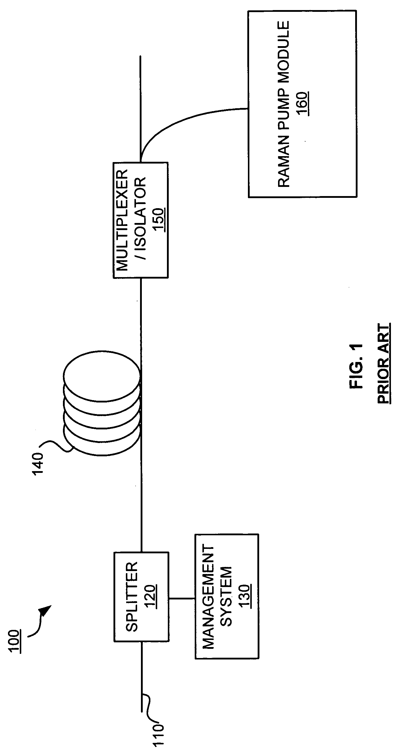
In spite of these benefits, however, the cost of components in a Raman amplifier may be prohibitive.
One problem with the distributed Raman amplifier 100 is that a high energy optical pump signal at a specific wavelength must be generated to produce Stimulated Raman Scattering.
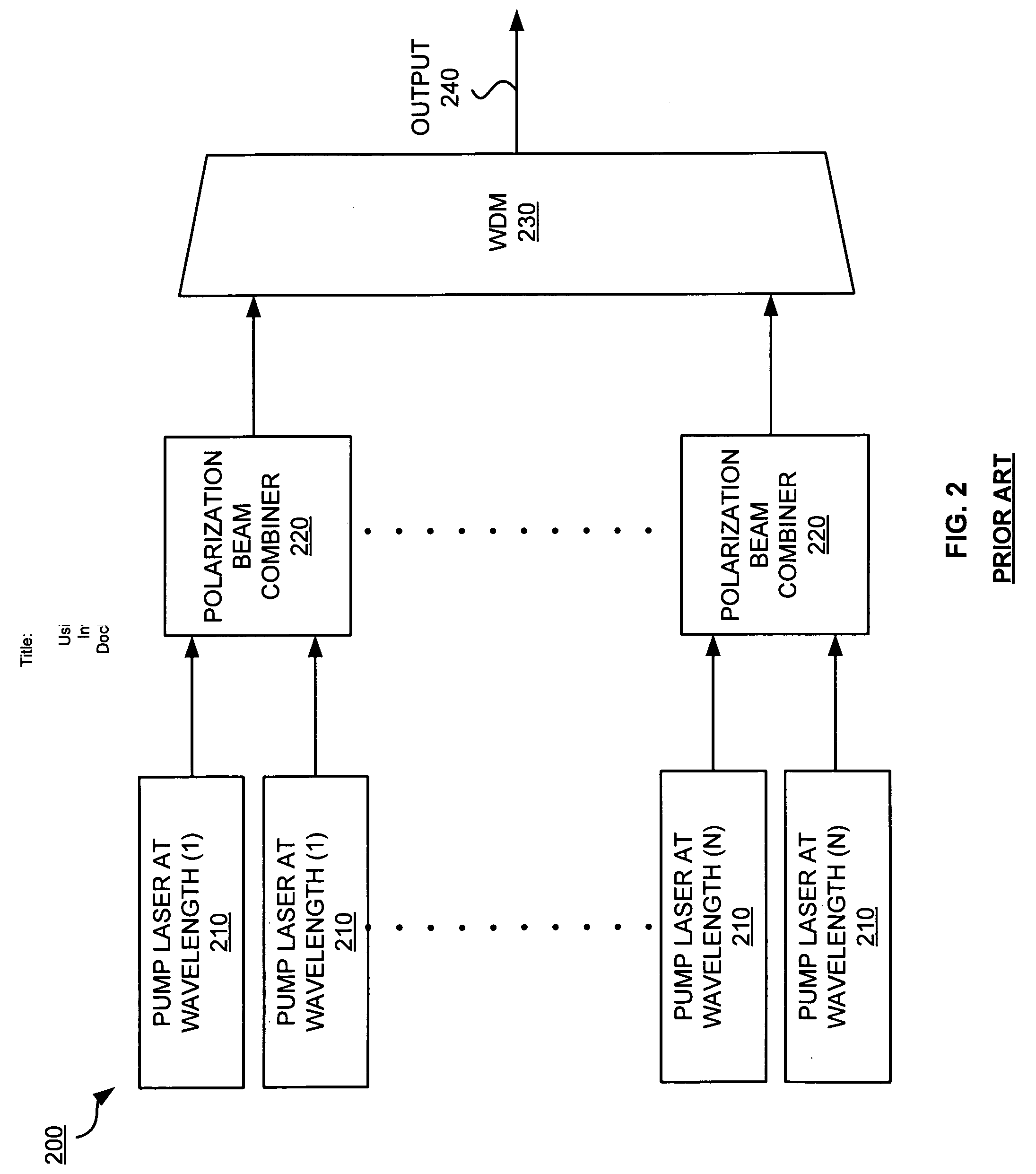
In this technique, multiple optical pump lasers are required for certain wavelengths to generate the desired effect of amplification which increases cost.
The process of adjustment and balance of optical pump lasers requires costly logistical support and offers an opportunity for error.
Further, additional optical pump lasers increase the chances of optical system failure due to component failure.

Method used


Image

  • Systems and methods for optical pumping using depolarizing filters
  • Systems and methods for optical pumping using depolarizing filters
  • Systems and methods for optical pumping using depolarizing filters

Examples


Embodiment Construction

[0021] The embodiments discussed herein are illustrative of one example of the present invention. As these embodiments of the present invention are described with reference to illustrations, various modifications or adaptations of the methods and / or specific structures described may become apparent to those skilled in the art. All such modifications, adaptations, or variations that rely upon the teachings of the present invention, and through which these teachings have advanced the art, are considered to be within the scope of the present invention. Hence, these descriptions and drawings should not be considered in a limiting sense, as it is understood that the present invention is in no way limited to only the embodiments illustrated.

[0022] Optical signal amplification is a common component of many optical communications systems. In optical signal amplification, a signal is amplified so that the original signal does not attenuate to a point where communications diminish or termina...


PUM


Abstract

An optical system comprises optical pump lasers, depolarizing filters and a multiplexer. A plurality of optical pump lasers generates a plurality of initial optical signals at different wavelengths. A plurality of depolarizing filters depolarize the plurality of initial optical signals. A multiplexer multiplexes the plurality of initial optical signals to form at least one optical pump signal. These systems and methods advantageously provide at least one optical pump signal with the required energy spread across multiple polarizations with fewer optical pump lasers. The reduction of optical pump lasers may eliminate the need to balance or adjust the power and polarization of each optical pump laser. Further, by reducing the number of optical pump lasers, the rate of component failure also reduces. As a result, these systems and methods are more reliable, may reduce maintenance costs, and may reduce the size as well as weight of the optical pumping system.

Description

BACKGROUND [0001] 1. Field of the Invention [0002] The present invention relates to optical pumping using depolarizing filters, and more particularly, to systems and methods for optical pumping of a signal through depolarizing filters within an optical amplification system. [0003] 2. Description of the Prior Art [0004] New markets and uses are constantly being developed to take advantage of the benefits of optical communications. However, to take advantage of these benefits, optical communications often require systems that inject optical pump signals into an optical fiber to amplify optical data signals. An example of such a system includes a Raman amplifier which amplifies a desired communications signal and prevents communications signal attenuation. In spite of these benefits, however, the cost of components in a Raman amplifier may be prohibitive. [0005]FIG. 1 is an illustration of a distributed Raman amplifier in the prior art. In FIG. 1, an optical signal path 110 receives an...

Claims


Application Information

Patent Timeline
IPC IPC(8): H01S3/091
CPCH01S3/005H01S3/06754H01S3/094096H01S3/302H01S2301/04H01S3/10015H01S3/13013
Inventor CHAPUT, BRIAN
Owner SANMINA-SCI CORPORATION
Learn More