Method of producing nanoparticles using a evaporation-condensation process with a reaction chamber plasma reactor system

a plasma reactor and evaporation condensation technology, which is applied in the direction of liquid-gas reaction process, chemical/physical/physico-chemical process, synthetic resin layered products, etc., can solve the problems of large pressure gradient, difficult to obtain desired properties, large and expensive pumps, etc., and achieve the effect of reducing the temperature of the reaction mixture and the produ

Inactive Publication Date: 2006-07-20
EI DU PONT DE NEMOURS & CO
View PDF13 Cites 101 Cited by
  • Summary
  • Abstract
  • Description
  • Claims
  • Application Information

AI Technical Summary

Benefits of technology

[0031] (e) immediately injecting quench gas through the quench gas inlet tubes as the reaction mixture flow enters the quench zone so that particle coagulation and coalescences is reduced and temperature of the reaction mixture and product is decreased; and
[0033] This invention also provides a reaction chamber for minimizing flow recirculation in a reactor, the reaction chamber comprising an axially spaced entrance and an exit wherein in the vicinity of the exit the homogenizer converges to nozzle tip, the entrance of the homogenizer being aligned with the inlet to the reaction chamber and the homogenizer being inserted within the reaction chamber and held in place by a homogenizer holder such that the homogenizer extends from the inlet end of the reaction chamber securely fitting against the inlet end for at least a portion of the homogenizer's overall length and wherein the homogenizer comprising two zones: (i) a spacer zone having a length, L1, extending from the reaction chamber chamber entrance and ending where one or more reactant inlet tubes are positioned, after having passed through a wall of the reaction chamber, to deliver one or more reactants into the reaction chamber so the reactants contact the hot carrier gas and (ii) a homogenization zone extending from the reactant inlet tubes' location to a position down stream of the quench gas inlets; and wherein carrier gas and reactants mix and react in the homogenization zone and pass through the flow homogenization exit nozzle wherein L1 of the spacer zone must be long enough to have the hot gas flow attached to walls of the reaction chamber before the hot gas reaches the reactant inlets and the overall length (L1+L2) of the reaction chamber is designed to a residence time sufficient that before gas flow exits the homogenizer: gas flow in the reaction chamber has achieved a near one-dimensional flow and concentration profile.

Problems solved by technology

For most of the applications, it is very difficult to obtain the desired properties when the nanoparticles employed are either widely distributed in primary particle size or highly aggregated or both.
A serious difficulty with the jet expansion as taught in the prior art is that these techniques require large pressure gradients to accelerate the flows; necessitating large and expensive pumps.
In addition, the discharging of hot gas into an open domain, such as a plasma gas entering a reaction chamber, results in a jet that will entrain local fluid, causing a recirculation region.
This may greatly accelerate aggregation, sintering and coalescence of the particles, all of which are generally undesirable.
The issue here is not the nozzle per se, but the large pressure drop required for such flow, which can be expensive to maintain and difficult to scale.

Method used


Image

  • Method of producing nanoparticles using a evaporation-condensation process with a reaction chamber plasma reactor system
  • Method of producing nanoparticles using a evaporation-condensation process with a reaction chamber plasma reactor system
  • Method of producing nanoparticles using a evaporation-condensation process with a reaction chamber plasma reactor system

Examples


examples

[0076] Unless otherwise specified, all chemicals and reagents were used as received from Aldrich Chemical Co., Milwaukee, Wis.

example a

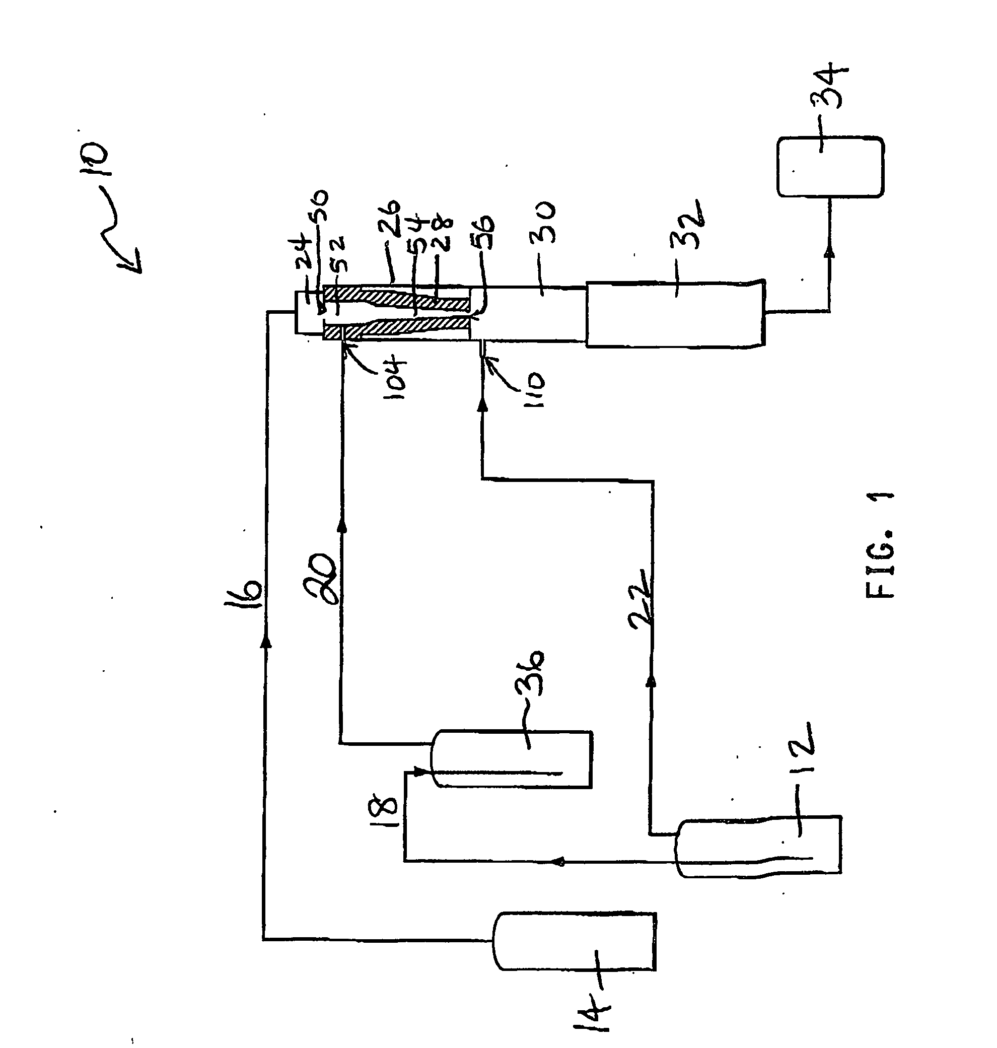
[0077] TiCl4 vapor was thoroughly premixed with O2 by bubbling O2 at a rate of 10 l / min through a cylinder maintained at room temperature that contains liquid TiCl4. The mixture of TiCl4 and O2 was then introduced into the reaction chamber through three equally spaced radial ports that are 0.32 cm in diameter. The reaction chamber was of cylindrical shape (2.52 cm in diameter, 7.56 cm in height) and did not contain a homogenizer. Gaseous titanium dioxide was formed by TiCl4 oxidation reaction. TiO2 aerosol particles were formed by gas-phase nucleation of the TiO2 vapor followed by condensation and coagulation. At the end of the reaction chamber, room temperature O2 was introduced radially into the quenching chamber at a rate of 30 l / min where the high temperature aerosol stream was lowered by mixing with the room temperature quenching gas. The quenching chamber is of cylindrical shape (2.52 cm in diameter, 20.16 cm in height). Downstream from the quenching chamber, TiO2 particles we...

example 1

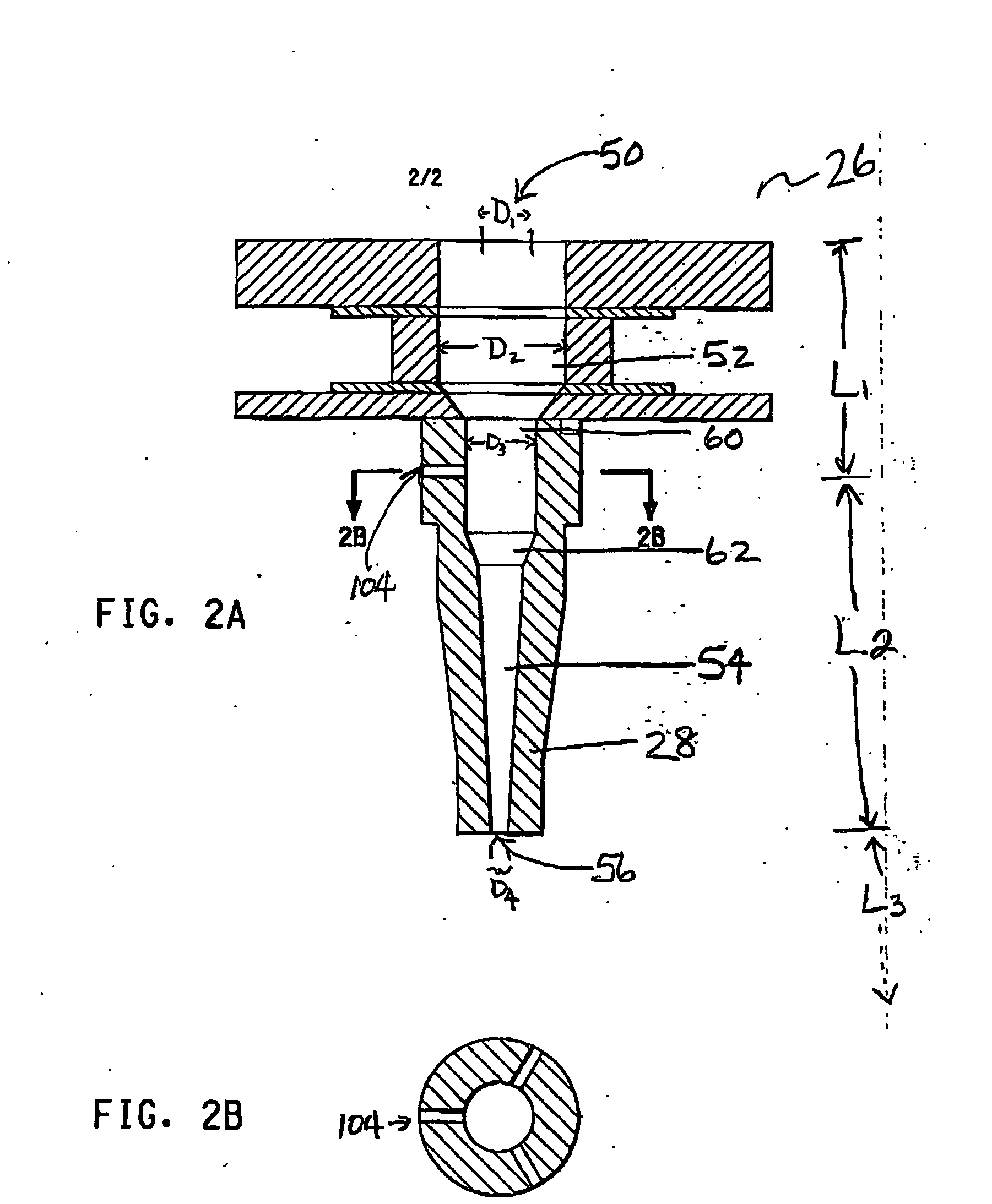
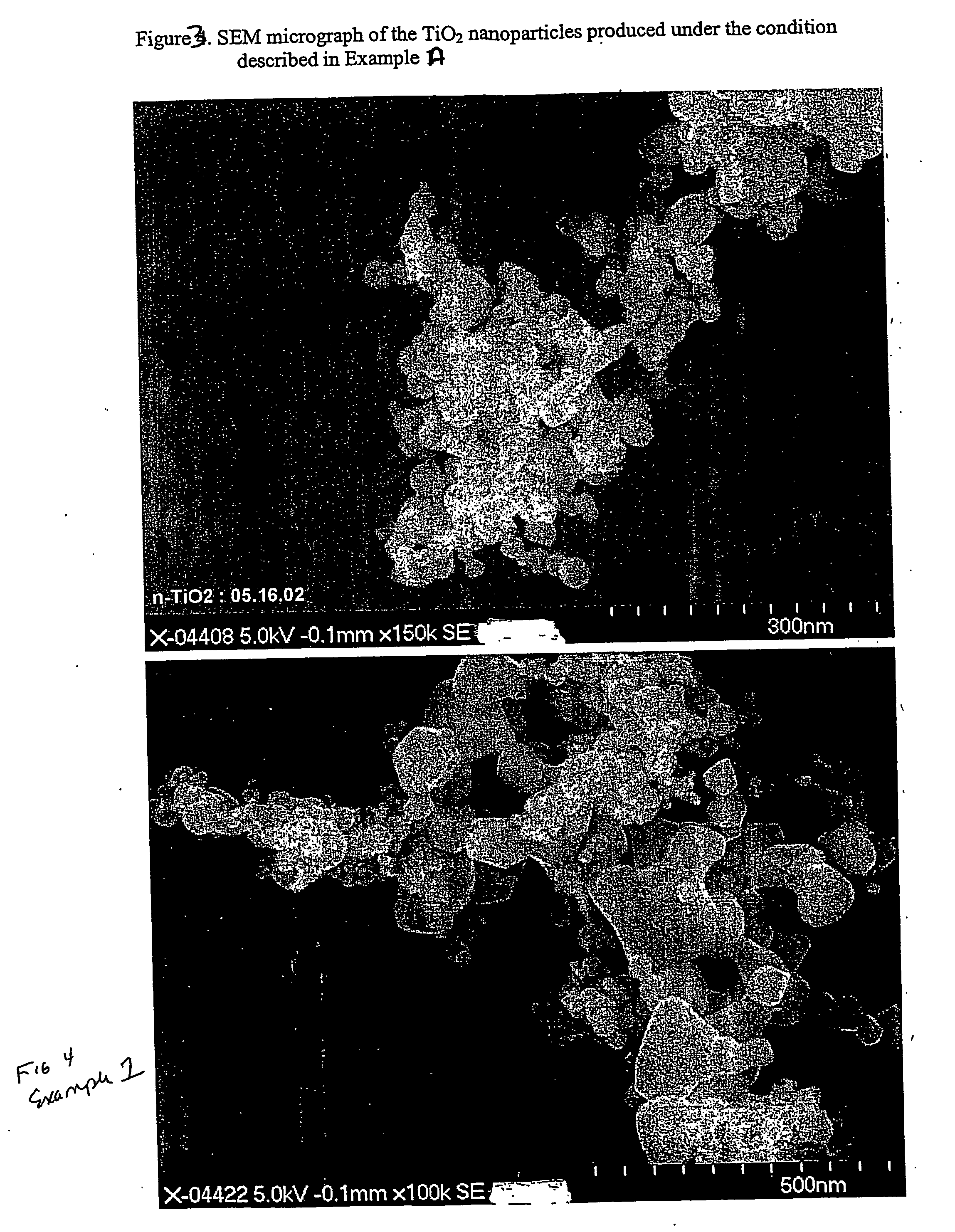
[0078] The process of Example A was repeated except that (1) a homogenizer (as shown in FIG. 2a) was installed in the reaction chamber (; (2) the diameter of the TiCl4 injection ports was reduced to 0.02 cm. The dimensions of the homogenizer and the properties of the resulting TiO2 particles are listed in the Table. FIG. 4 is an SEM micrograph of the TiO2 nanoparticles produced under this condition.


PUM

PropertyMeasurementUnit
particle sizeaaaaaaaaaa
sizeaaaaaaaaaa

Abstract

The present invention provides a method and apparatus for the controlled synthesis of nanoparticles using a high temperature process. The reactor chamber includes a high temperature gas heated by means such as a plasma torch, and a reaction chamber. The homogenizer includes a region between the reactant inlets and the plasma (the spacer zone) to ensure that feeds from the reactant inlets are downstream of the recirculation zone induced by the high temperature gas. It also includes a region downstream of the reactant inlets that provides a nearly I dimensional (varying only in the axial direction) flow and concentration profile in the reaction zone to produce nanoparticles with narrow size distribution.

Description

CROSS-REFERENCE TO RELATED APPLICATIONS [0001] Cross-reference is made to U.S. provisional application No. 60 / 434158 filed on Dec. 17, 2002, which is incorporated herein by reference in its entirety.FIELD OF THE INVENTION [0002] The present invention provides a method and apparatus for the controlled synthesis of nanosize particles using a high temperature process. The reactor chamber of the present invention includes a high temperature heating means such as a plasma torch, and a novel reaction chamber. The reaction chamber is a portion of the reactor chamber having a region between the hot gas inlet and the reactant inlets (the spacer zone) to ensure that feeds from the reactant inlets enter the reactor chamber downstream of the recirculation zone induced by the high temperature gas discharge. This shift in the location where the reactant gas is contacted by a hot carrier gas provides a nearly 1-dimensional (varying only in the axial direction) flow and concentration profile in the...

Claims


Application Information

Patent Timeline
Patent Type & Authority Applications(United States)
IPC IPC(8): C22B4/00B32B27/04C21B11/10B01JB01J2/04B01J19/08B01J19/24B01J19/26B82B3/00C01G1/02C01G23/07
CPCB01J19/088B01J19/26B01J2219/0871B01J2219/0883B01J2219/0894B22F9/28B22F2998/00B82Y30/00C01G1/00C01G1/02C01G23/07C01G23/075C01P2004/03C01P2004/64C01P2006/12C01P2006/64C22B4/005C22B34/1222C22B34/1227B22F2202/13B01J19/08B82B3/00B82Y40/00Y02P10/20
Inventor DE LA VEAUX, STEPHAN CLAUDEZHANG, LU
Owner EI DU PONT DE NEMOURS & CO
Why Eureka
Try Eureka