
Detection method and apparatus for detecting microbial growth

a detection method and microbial technology, applied in the direction of liquid/fluent solid measurement, fluid pressure measurement, peptide, etc., can solve the problems of small changes in the thickness of the glass wall, cross-contamination within the vial, and relatively high cost of the vial

Active Publication Date: 2006-07-20
BECTON DICKINSON & CO
View PDF8 Cites 15 Cited by
  • Summary
  • Abstract
  • Description
  • Claims
  • Application Information

AI Technical Summary

Benefits of technology

[0004] One solution to the above problems includes the use of a non-invasive infrared microorganism detection instrument in which special vials having infrared-transmitting windows are utilized. These vials, however, are relatively expensive. In yet another solution, glass vials are transferred to an infrared spectrometer by an automated manipulator arm and measured through the glass vial. The disadvantage of this system is that, due to the high infrared absorption of glass, small changes in the glass wall thickness can generate large errors in the measured headspace gas absorption. These problems can be partly reduced by utilizing high-quality glass vials, but this measure results in relatively high vial cost.

Problems solved by technology

Monitoring the carbon dioxide content can be accomplished by methods well established in the art; however, most of these methods require invasive procedures which can result in the well-known problem of cross-contamination within the vial.
These vials, however, are relatively expensive.
The disadvantage of this system is that, due to the high infrared absorption of glass, small changes in the glass wall thickness can generate large errors in the measured headspace gas absorption.
These problems can be partly reduced by utilizing high-quality glass vials, but this measure results in relatively high vial cost.
However, in such solutions, errors can occur if any of the light source, photodetector, filters, or sensor show aging effects over time, which would vary the intensity response.

Method used


Image

  • Detection method and apparatus for detecting microbial growth
  • Detection method and apparatus for detecting microbial growth
  • Detection method and apparatus for detecting microbial growth

Examples


example

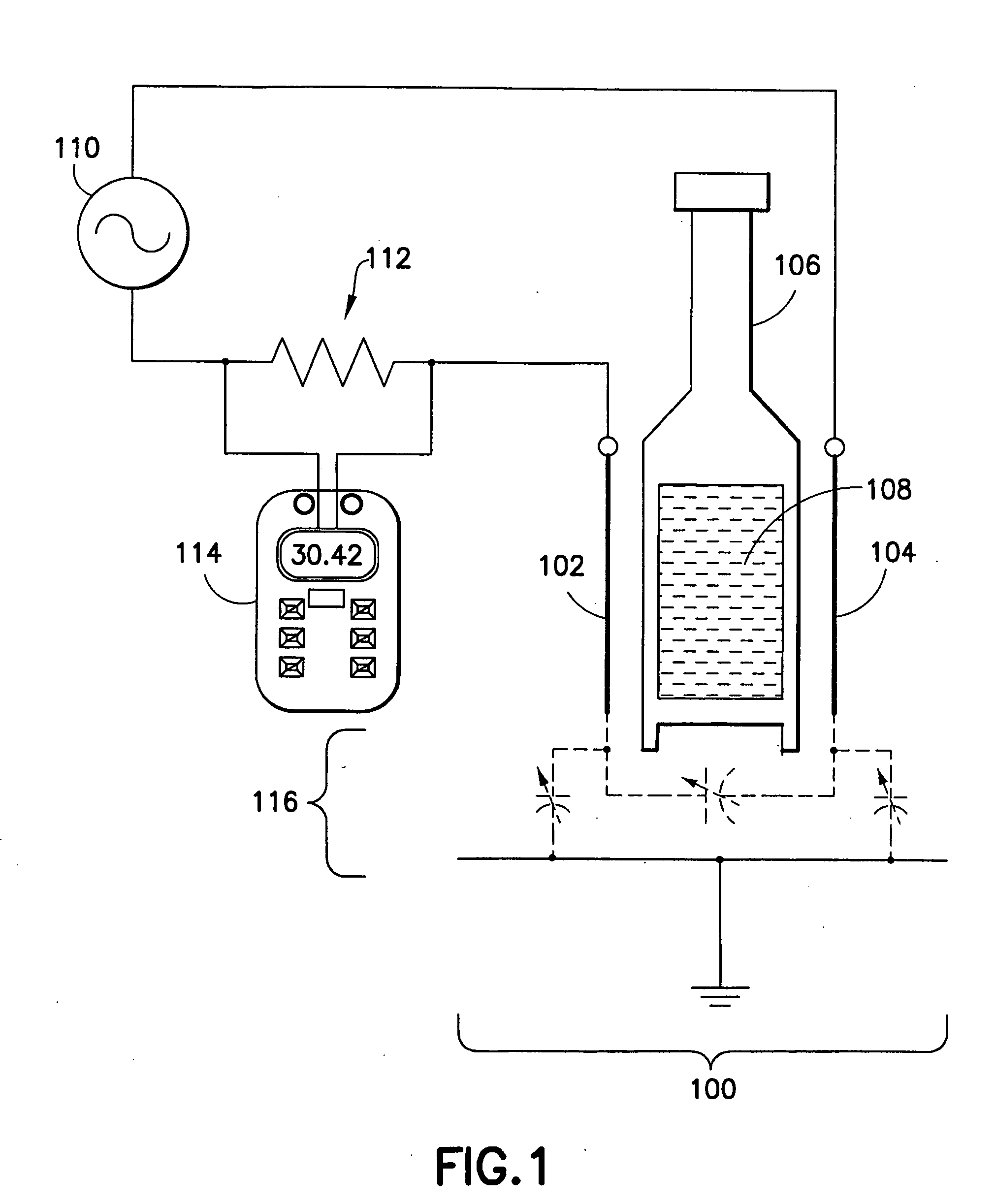
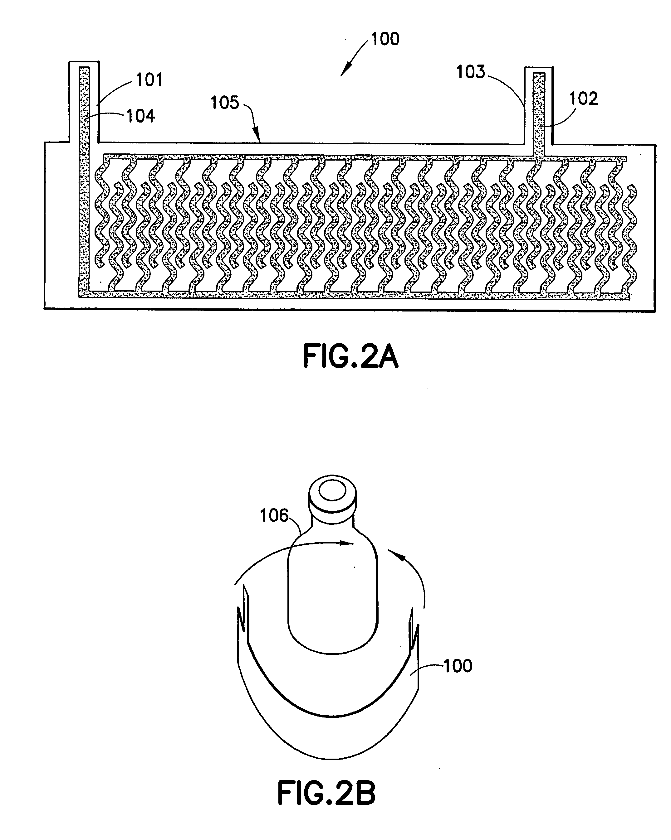
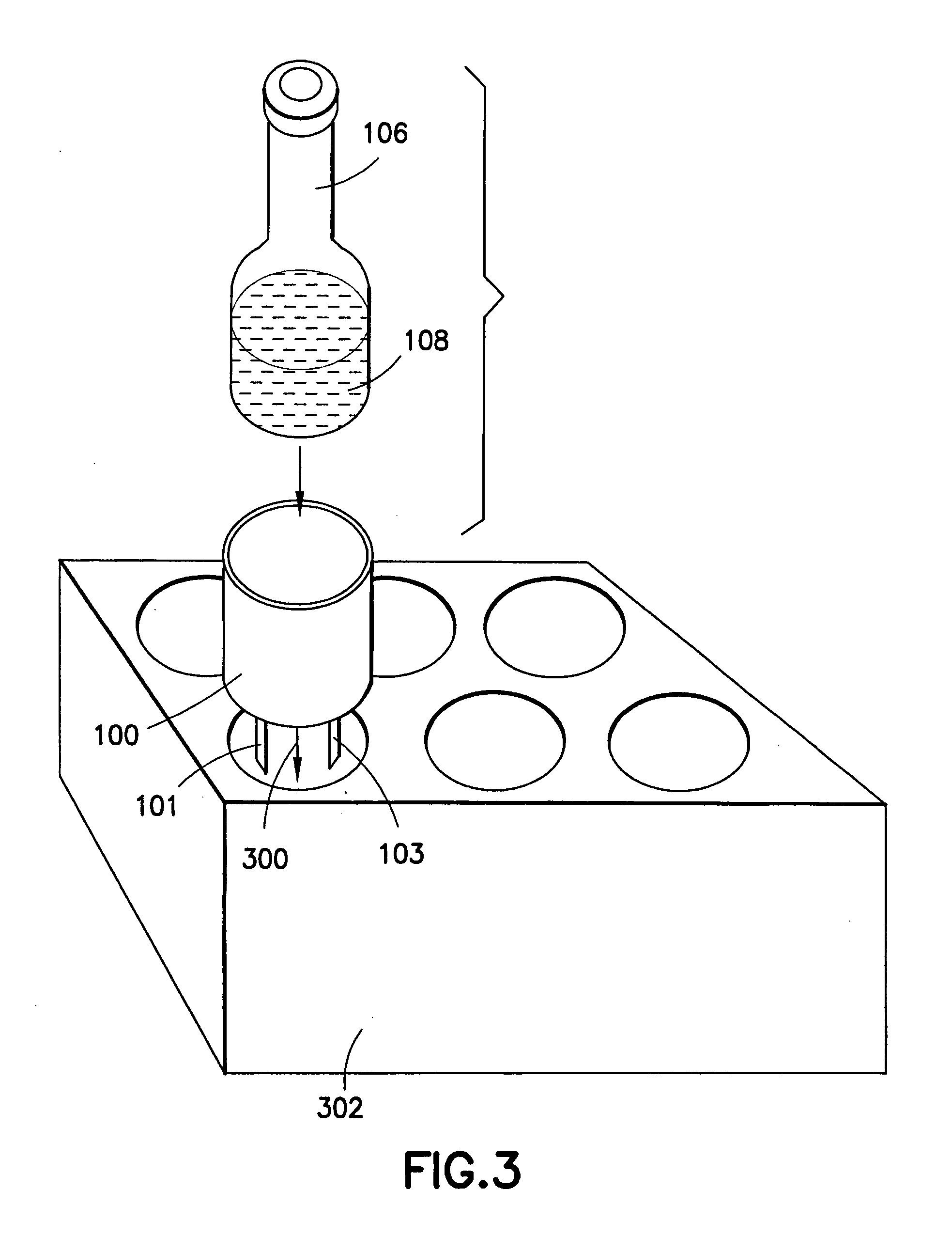
[0034] A BD BACTEC(tm) Plus Aerobic / F culture bottle was obtained. A single, flexible electrode of the type shown in FIG. 2A was assembled. Tin-coated copper adhesive tape was pre-cut to form the interdigitated fingers and placed on a 0.005 inch thick Mylar substrate. Electrical connections to the two electrodes were formed by two tabs extending from the fingers, and were connected to an electrical circuit board. The electrode was placed onto the bottle, to circumferentially surround it.

[0035] The electrode was attached to a Motorola 33794 Electric Field Imaging Device evaluation module, which is a device designed for sensing objects within its self-generating electric field. Data was logged by a personal computer running a LabView “virtual instrument” application specifically designed for the 33794 device. The program periodically sent a digital signal to the 33794 via a serial data connection, and the integrated circuit of the 33794 would measure the amount of field in the electr...


PUM

PropertyMeasurementUnit
Angleaaaaaaaaaa
Flexibilityaaaaaaaaaa
Electrical conductoraaaaaaaaaa

Abstract

A system and method is provided for non-invasively measuring changes in a specimen suspected of containing one or more microbes, by monitoring changes in the dielectric constant of the specimen caused by metabolic processes of such microbes.

Description

RELATED APPLICATION This application claims priority to U.S. Provisional Patent Application No. 60 / 639,366 filed Dec. 27, 2004, the disclosure of which is hereby incorporated by reference.FIELD OF THE INVENTION [0001] The present invention relates to a system and method to measure a change in a biological sample in a non-invasive manner to avoid contamination of the sample. BACKGROUND OF THE INVENTION [0002] Currently, the presence of biologically active agents such as bacteria in a patient's body fluid, and especially in blood, is determined using blood culture vials. A small quantity of blood is injected through an enclosing rubber septum into a sterile vial containing a culture medium and the vial is then incubated and monitored for bacterial growth. [0003] Common visual inspection of the culture vial then involves monitoring the turbidity or observing eventual color changes of the liquid suspension within the vial. Known instrument methods can also be used to detect changes in t...

Claims


Application Information

Patent Timeline
IPC IPC(8): C12Q1/04
CPCG01N27/221B01L7/52G01N33/48735C12N13/00G01N27/22C12M35/02
Inventor BACHUR, NICHOLAS R. JR.NEUBERT, JOHN W.
Owner BECTON DICKINSON & CO
Learn More