Intake flow control apparatus for an internal combustion engine

a flow control and internal combustion engine technology, applied in mechanical devices, electric control, machines/engines, etc., can solve the problems of difficult to meet this requirement, increase air flow resistance, and limit in shortening the intake passage, so as to reduce the number of parts, high rigidity, and high strength

Inactive Publication Date: 2006-07-27
HONDA MOTOR CO LTD
View PDF2 Cites 6 Cited by
  • Summary
  • Abstract
  • Description
  • Claims
  • Application Information

AI Technical Summary

Benefits of technology

[0063] According to the seventeenth aspect of the invention, since the casing of the fuel injector, fixed to the body of the internal combustion engine, guides and moves the air flow regulator in the intake axis direction, it is not necessary to use any special guide member and hence the number of parts can be r

Problems solved by technology

If a throttle valve is disposed within the intake passage, a limit is encountered in shortening the intake passage.
However, it is difficult to meet this requirement where the throttle valve is disposed within the intake passage.
Moreover, if a rotary opening/closing valve or the like is present within an intake passage, the air flow resistance increases, because the valve mechanism disturbs the smooth flow of intake air.
As a result, a large amount of power is required for moving the air guide member, and thus it is not easy to control the amount of intake air.
Accordingly, a motor

Method used


Image

  • Intake flow control apparatus for an internal combustion engine
  • Intake flow control apparatus for an internal combustion engine
  • Intake flow control apparatus for an internal combustion engine

Examples


first embodiment

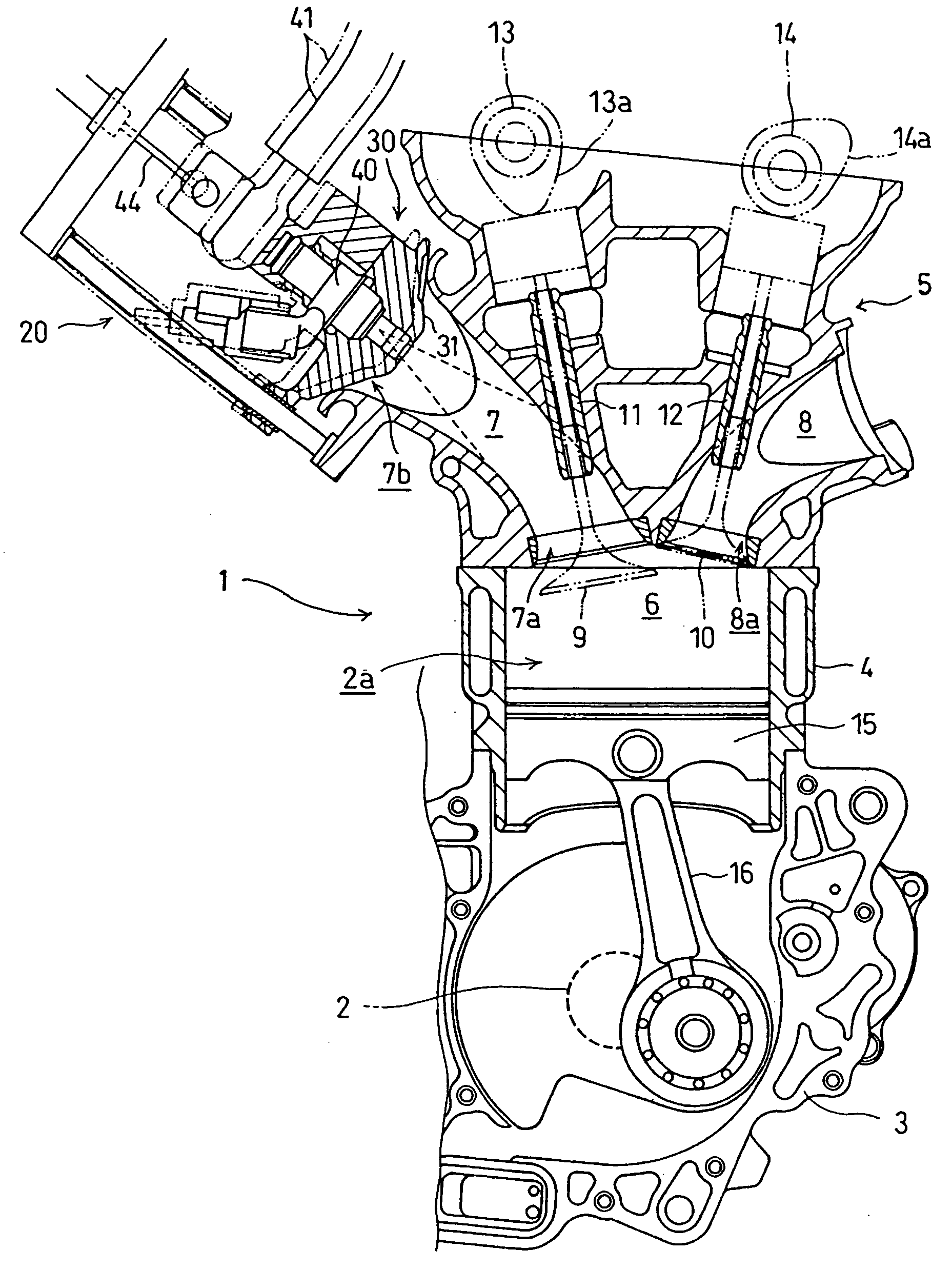
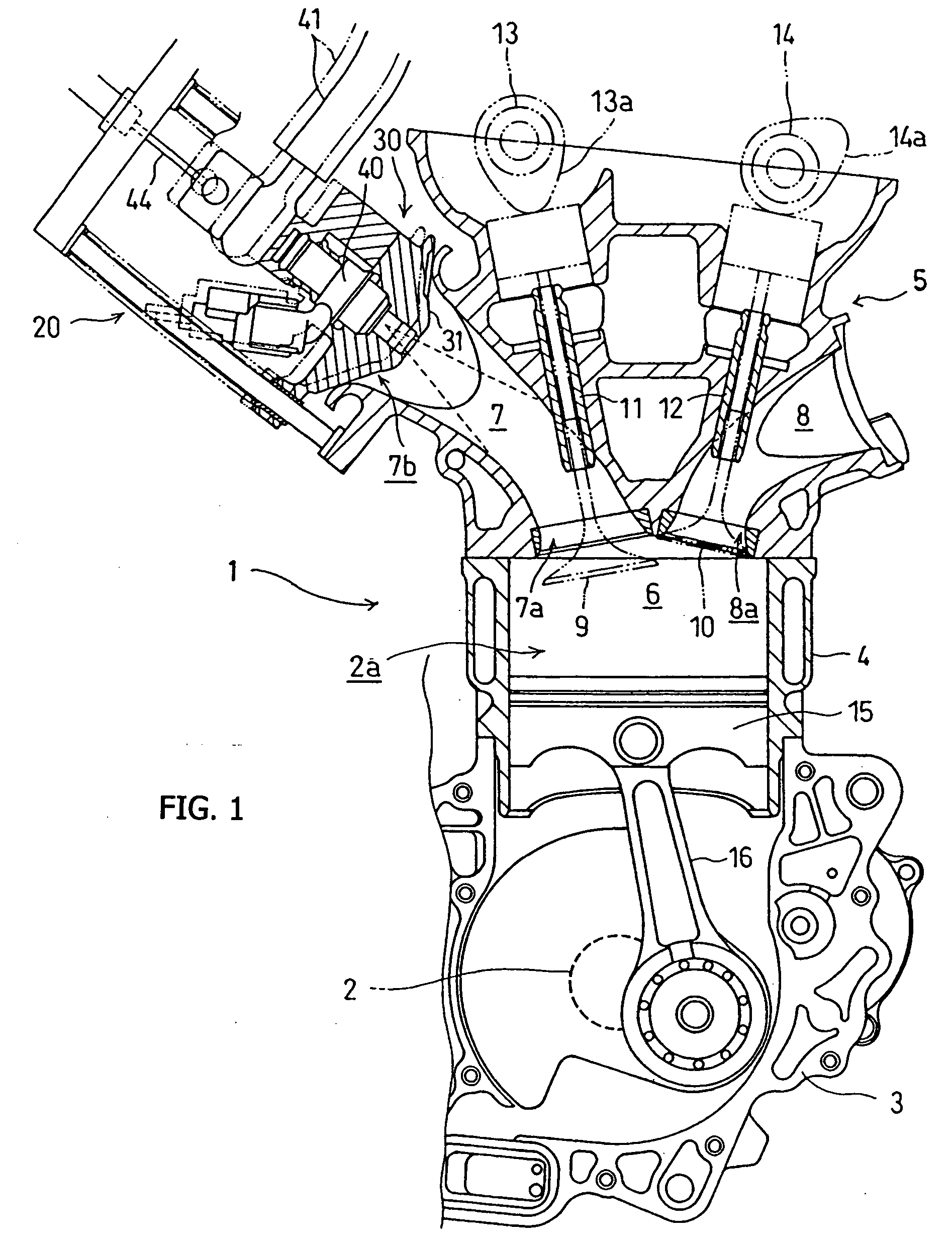
[0106] the present invention will be described below with reference to FIGS. 1 to 4. An internal combustion engine 1 related to this embodiment is a four-stroke cycle DOHC (Double Over Head Camshaft) type internal combustion engine, suitable to be mounted on a motorcycle.

[0107]FIG. 1 is a partial sectional view of the internal combustion engine 1, taken along a vertically extending plane. In the figure, a cylinder block 4 and a cylinder head 5 are superimposed one on the other in this order, and are combined with a crank case 3 in which a crankshaft 2 is rotatably mounted. A piston 15 is adapted to reciprocally slide within a cylinder bore 2a of the cylinder block 4. The piston 15 is connected through a connecting rod 16 to a crank pin 2a of the crankshaft 2, whereby the reciprocating motion of the piston 15 is converted to rotation of the crankshaft 2.

[0108] A combustion chamber 6 is formed in the cylinder head 5 above the piston 15, The cylinder head 5 is integrally superimposed ...

second embodiment

[0133] Next, the present invention, which is illustrated in FIG. 5, will be described below.

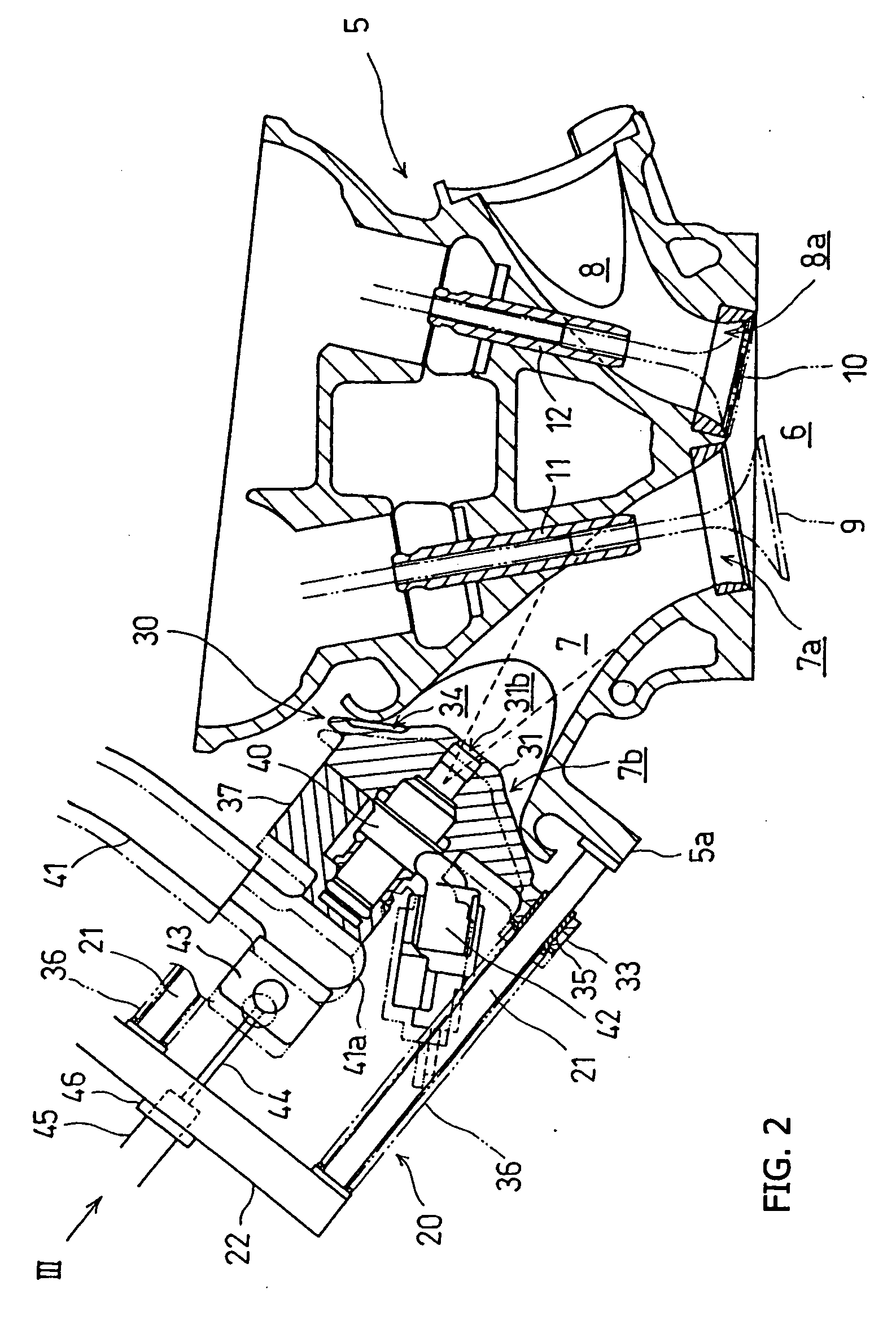
[0134] The second embodiment is a modification of the above-described first embodiment. In the first embodiment, when the valve element 31 of the intake air flow regulator 30 comes into abutment against the intake passage opening 7b, the grooves 34 formed in the conical surface of the valve element 31 serve as air bypass passages to reduce the negative pressure in the intake passage 7. On the other hand, in the second embodiment, an air bypass passage is constituted by restricting movement of the valve element of the air flow regulator.

[0135] The intake flow control apparatus of this second embodiment is constituted by the same members as in the first embodiment except that grooves are not formed in a conical surface of a valve element 51 of an air flow regulator 50. The same members as in the first embodiment are identified by the same reference numerals as in the first embodiment.

[0136] S...

third embodiment

[0139] Next, the present invention will be described below with reference to FIG. 6.

[0140] Substantially the same members as in the first embodiment are used except the drive mechanism for moving the air flow regulator and the valve element of the air flow regulator. The same members as in the first embodiment are identified by the same reference numerals as in the first embodiment.

[0141] In a valve element 61 of an air flow regulator 60 used in this embodiment, grooves are not formed in a conical surface of the valve element, but instead, a communication hole 62 is formed through the valve element 61, to provide communication between the conical surface side and the back side thereof. The communication hole 62 extends through the valve element 61 in a direction substantially parallel to the axis thereof. The communication hole 62 is used as an air bypass passage, which provides communication between the interior and the exterior of the intake passage 7.

[0142] Further in this embo...


PUM


Abstract

An intake flow control apparatus for an internal combustion engine eases operation of an air flow regulator and permits use of a short intake passage, thus providing a high output. The intake flow control apparatus includes an air routing member having an intake passage formed therein, and an air flow regulator opposed to an upstream-side opening of the intake passage. The air flow regulator moves in an intake axis direction while being guided by a light-weight guide structure to control the amount of intake air supplied. The air flow regulator may include plural valve elements different in operation timing, in which a valve actuator successively actuates the plural valve elements in accordance with a throttle operation to control the amount of intake air. The apparatus also includes a vacuum moderating structure for reducing the effective strength of a vacuum applied to the air flow regulator.

Description

CROSS-REFERENCE TO RELATED APPLICATIONS [0001] The present invention claims priority under 35 USC 119 based on Japanese patent applications No. 2005-014710, No. 2005-014711, and No. 2005-014712, all filed on Jan. 21, 2005. The subject matter of each of these priority documents, including written description, drawings, and claims, is incorporated by reference herein. BACKGROUND OF THE INVENTION [0002] 1. Field of the Invention [0003] The present invention relates to an intake air flow regulator apparatus for use on an internal combustion engine. More particularly, the present invention relates to an air flow regulator apparatus in which a guide structure guides axial movement of an air flow regulator plug in response to movement of a throttle actuator, to control air flow through an intake passage and to a combustion chamber. [0004] 2. Description of the Background Art [0005] Within an intake passage for introducing intake air into a combustion chamber of an internal combustion engin...

Claims


Application Information

Patent Timeline
IPC IPC(8): F02D9/08F02M61/14
CPCF02D9/02F02D9/12F02M9/127
Inventor ISHIDA, SHUICHITAKAHASHI, KATSUNORIKUNIKIYO, KATSUHIRONISHIYAMA, RYOHSAKUUEDA, HIROYA
Owner HONDA MOTOR CO LTD
Why Eureka
Try Eureka