High efficiency LED optical engine for a digital light processing (DLP) projector and method of forming same

a technology of optical engine and projector, which is applied in the direction of projectors, color television details, instruments, etc., can solve the problems of low efficiency of led optical engine, inability to drive color wheel, and inability to meet the needs of the user,

Active Publication Date: 2006-07-27
JABIL CIRCUIT INC
View PDF18 Cites 61 Cited by
  • Summary
  • Abstract
  • Description
  • Claims
  • Application Information

AI Technical Summary

Problems solved by technology

One drawback of these types of prior art systems is that the color gamut of the projection system, with color wheel, is often limited due to the spectrum distribution of the white light source.
Another inherent disadvantage is that the motor for driving the color wheel can be a source of ambient noise.
However, there are some drawbacks with these types of short arc type discharge lamps.
One of these is that all of the light except blue, green, and red will be filtered out resulting in a loss in efficiency.
This has the effect of making the system very bulky and complex.
Furthermore, there is a significant amount of ultraviolet (UV) and infrared (IR) light emitted from these lamps.
To eliminate UV and IR light emitted from the lamp, UV / IR filters must be used that result in an increase in system complexity.
In practice, it is often a challenge to get a good uniform light beam from the LED source with the least amount of optical loss.
Optical loss is typically caused by a fly-eye lens array or waveguides integrated into the projector illumination system.
One disadvantage in this type of implementation is that the coupling between LEDs and fibers is often a problem.
Practically, due to coupling and transmitting losses, it is difficult to efficiently couple light emitting from LED arrays to corresponding fiber bundles and light pipes.
The main problem with this system is that some light from the LEDs cannot enter the corresponding lens of the first and second fly-eye lenses due to aberration and aperture limitation of lens arrays.
Thus, a portion of illumination light falls outside of the panel area resulting in low light efficiency and low contrast.
Accordingly, it has proven to be a challenge to provide an LED optical system for DMD projector that overcomes the shortcomings of the existing prior art LED illumination systems.

Method used


Image

  • High efficiency LED optical engine for a digital light processing (DLP) projector and method of forming same
  • High efficiency LED optical engine for a digital light processing (DLP) projector and method of forming same
  • High efficiency LED optical engine for a digital light processing (DLP) projector and method of forming same

Examples


Embodiment Construction

[0021] The present description is directed in particular to elements forming part of, or cooperating more directly with, apparatus in accordance with the invention. As will be understood by those familiar with the art, aspects of the invention may be embodied in other specific forms without departing from the scope of the invention as a whole. Accordingly, the disclosures and descriptions herein are intended to be illustrative, but not limiting, of the scope of the invention which is set forth in the following claims.

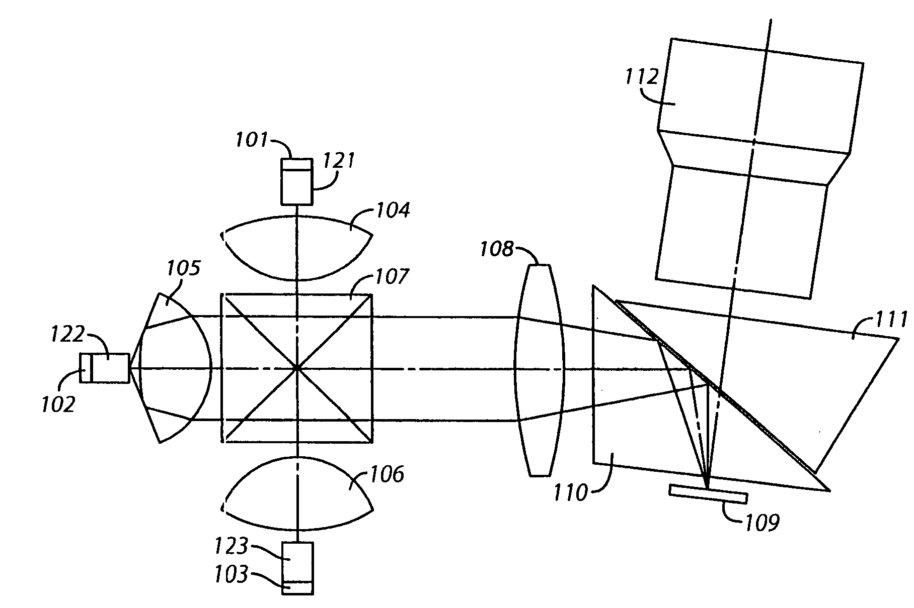
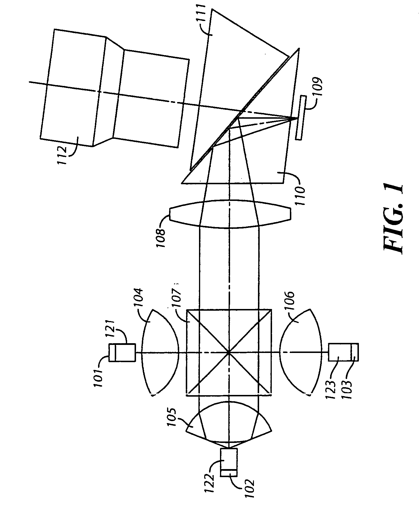
[0022]FIG. 1 is a block diagram for illustrating the schematic configuration of a red, green and blue (RGB) LED optical engine for a digital micro-mirror device (DMD) based image presentation or projection device, such as a rear projection television or front projector, according to the preferred embodiment of the invention. This embodiment of the optical engine comprises a substantially red LED panel 101, a substantially green LED panel 102, a substantially blue LED p...


PUM


Abstract

An optical light engine (100) includes one or more light-emitting diode (LED) panels (101, 102, 103) that are combined into a common path and directly imaged onto panel device to provide a source of light to a microdisplay panel (109). Preferably, the LED panel (101, 102, 103) is shaped such that the aspect ratio of light propagating the LED panel is substantially equal to the light received at the microdisplay panel (109). An aspect ratio of 4:3 or 16:9 is typically selected in view of the sizes of the LED panels used in the light engine.

Description

CROSS-REFERENCE TO RELATED APPLICATION [0001] Priority for this application is based upon Provisional Patent Application Ser. No. 60 / 646,779, filed Jan. 25, 2005, entitled High Efficiency LED Optical Engine for DLP Projector and assigned to Jabil Circuit, Inc.1. FIELD OF THE INVENTION [0002] This invention generally relates to an optical engine for a projector type display system and, more specifically, an optical engine with light-emitting diodes (LEDs) as light source used in connection with a digital micro-mirror device (DMD) based projection display system. 2. BACKGROUND OF THE INVENTION [0003] In recent years, digital projection systems using spatial light valve modulators, including DMDs and transmissive liquid crystal display, have been receiving much attention. These types of systems provide a high standard of display performance including high resolution, high brightness and a high contrast ratio. The conventional DMD projection display system includes at least a light sour...

Claims


Application Information

Patent Timeline
Patent Type & Authority Applications(United States)
IPC IPC(8): G03B21/00
CPCG02B27/1033G02B27/145G02B27/149G03B21/28H04N9/3144H04N9/315
Inventor MOREJON, ISRAEL J.ZHAI, JINHUILI, HAIZHANG
Owner JABIL CIRCUIT INC
Why Eureka
Try Eureka