Multi-spectral techniques for defocus detection

a multi-spectral technique and defocus detection technology, applied in the field of integrated circuit processing, can solve the problems of local or global focus problems, full-field focus problems, and suffer from microcircuit yield loss, so as to improve the sensitivity to extended defocus defects and reduce cost. , the effect of increasing the sensitivity to defocus defects

Inactive Publication Date: 2006-07-27
KLA TENCOR TECH CORP
View PDF4 Cites 37 Cited by
  • Summary
  • Abstract
  • Description
  • Claims
  • Application Information

AI Technical Summary

Benefits of technology

[0020] It is a further object of this invention to provide an improved method and apparatus for defocus detection which has lowered cost.
[0021] It is a further object of this invention to provide an improved method and apparatus for defocus detection which is more compact.
[0022] It is a further object of this invention to provide a method and apparatus for defocus detection which has increased sensitivity to extended defocus defects.
[0023] It is a further object of this invention to provide a method and apparatus for defocus detection which has increased sensitivity to defocus defects at smaller critical dimensions.

Problems solved by technology

This presents challenges in lithography, since out-of-focus exposure of features in photoresist smears the resist edges, as illustrated in FIG. 1.
If defocus is not detected, the microcircuit yields will suffer and the problem may not be detected until many steps later in the manufacturing process.
However, several factors can cause local or global focus problems: 1) The mounting of the reticle, i.e., the master pattern, may have a tilt.
This causes full-field focus problems.
2) The autofocus on the stepper may have a problem, which could cause a full-field defocus.
Either of these problems would result in a defocus region of about one inch dimension.
Color changes result from out-of-focus regions, due to the fact that changing the profile of diffraction grating edges can drastically change its scattering profile and therefore can cause an apparent color change.
The manual observation of color changes to detect defocused regions has severe limitations, due to the tri-stimulus color response of the eye, and its limited gray-scale depth at any wavelength.
It is expected that existing automated macro-inspection systems will find it progressively more and more difficult to detect defocus as the CD's shrink, because visible wavelengths are being used, and the diffraction gratings created by the photoresist will have a pitch much smaller than the wavelength of the light used.
Shorter wavelength light may damage the photoresist.

Method used


Image

  • Multi-spectral techniques for defocus detection
  • Multi-spectral techniques for defocus detection
  • Multi-spectral techniques for defocus detection

Examples


first embodiment

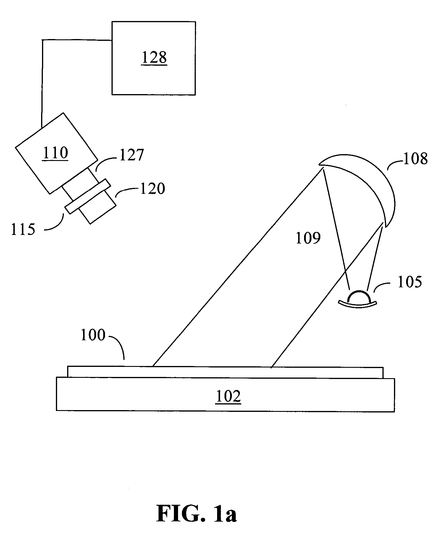
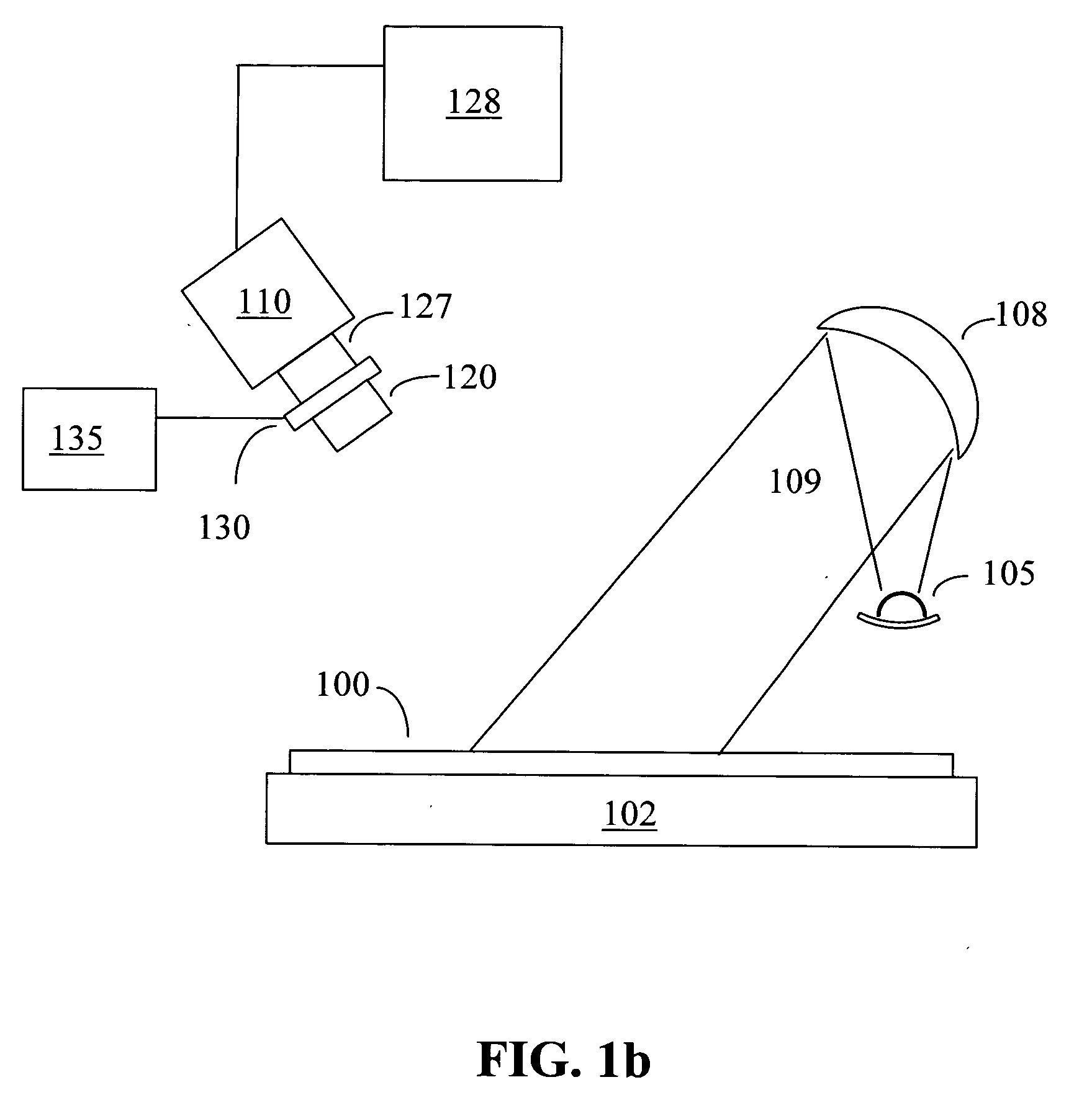
[0033] In the invention, defocus is detected by accumulating information about the detected scattered and diffracted light in an image of a region of interest of a wafer, collected for several different discrete wavelengths or for a wavelength spectrum. The information collected is both spatial (i.e., image), and wavelength spectral. This technique when employed with high spectral finesse, is often referred to as “hyperspectral imaging”.

[0034] A conventional monochromatic image is a function of the two spatial dimensions, I(x,y), where I is the intensity of the scattered and diffracted light from each point (x,y). In hyperspectral imaging, additional information is collected by varying wavelength λ, to yield an intensity image I(x,y,λ). In practice, the spectral information is typically not collected continuously, but rather at a number of discrete wavelengths. The spectral information can be derived in several ways:

a) Sequential Illumination with or Collection of Narrow-Band Ligh...

second embodiment

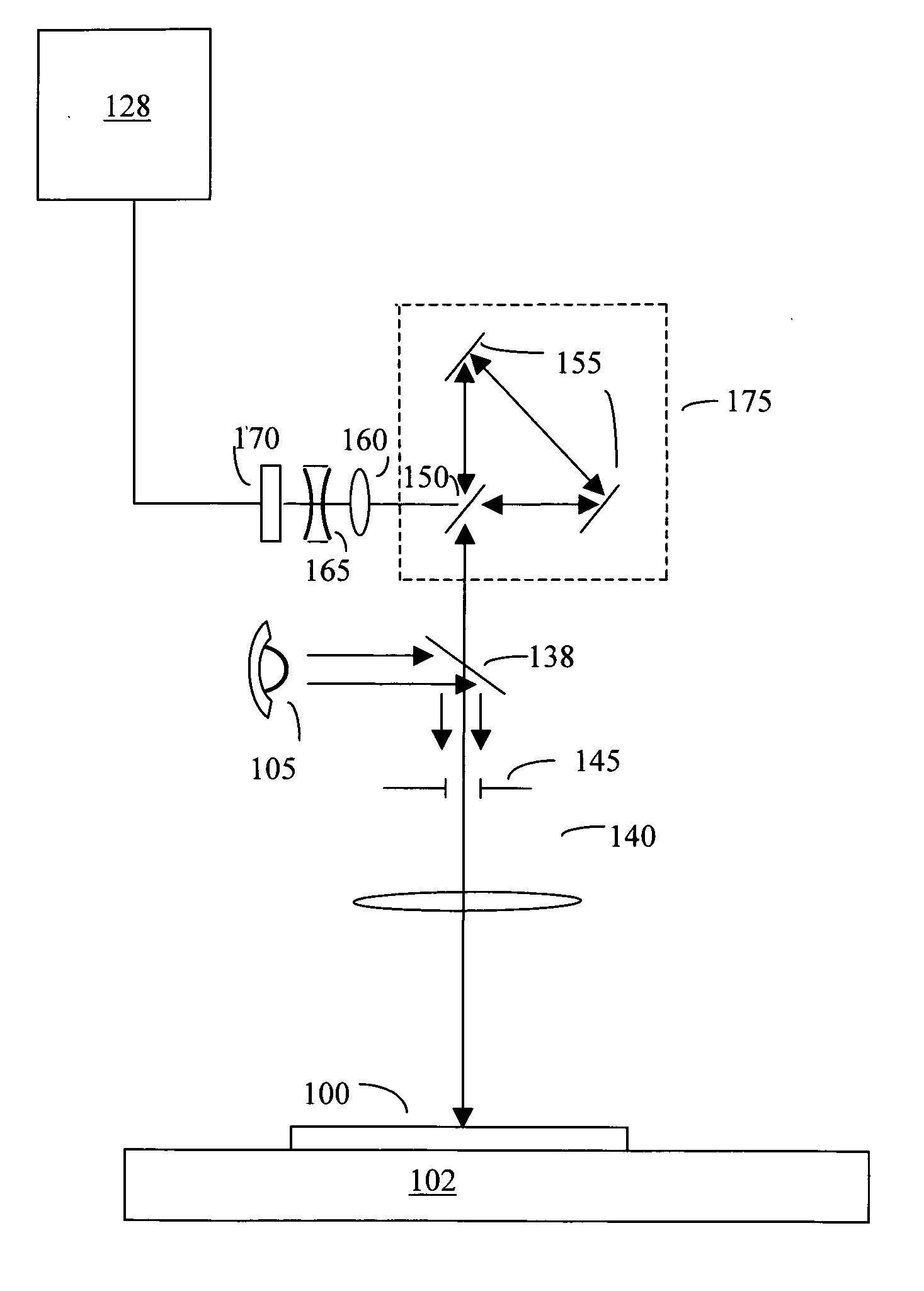
[0049] A basic principle of Fourier optics is that effects which are localized in physical space are diffuse in the Fourier domain, and that effects which are diffuse in physical space are localized in the Fourier domain. This phenomenon leads to the observation that transferring into Fourier space can enhance the detection and location of a diffuse effect such as diffuse defocus. the present invention provides an optical Fourier transform, i.e., a Fourier Transform of the spatial image, to achieve the transference.

[0050] When an object is illuminated with a plane wave, i.e., coherent monochromatic light, the light that impinges on it will diffract and scatter in such a way that, at infinity (far-field), a pattern of light is seen which is the spatial Fourier transform of the object being illuminated. No refractive or reflective optics is necessary for this effect to occur. On the surface of the object, information is purely spatial. At infinity, it is purely frequency information, ...


PUM


Abstract

A method and apparatus for improved defocus detection on wafers. The use of hyperspectral imaging provides increased sensitivity for local defocus defects, and the use of Fourier Space analysis provides increased sensitivity for extended defocus defects. A combination of the two provides improved overall sensitivity to local and extended defocus defects.

Description

CROSS-REFERENCE TO RELATED APPLICATION [0001] This application is related to U.S. Provisional Application No. 60 / 646,447, filed Jan. 24, 2005, and to U.S. Provisional Application No. 60 / 707,440, filed Aug. 11, 2005, and claims priority from both.FIELD OF THE INVENTION [0002] This invention relates to integrated circuit processing, and in particular to detection of focus errors caused by the lithography stepper / scanner. BACKGROUND OF THE INVENTION [0003] As integrated circuits become smaller and faster, Critical Dimensions (CD's) of devices must decrease. Current state-of-the-art requires critical dimensions of approximately 0.1 micron, and manufacturers are striving to move to lateral dimensions of 65 nm. Consequently, better lithographic resolution is required in order to print smaller features. As per the Rayleigh limit, resolution r is inversely proportional to Numerical Aperture (NA) according to the equation r∝λNA, where λ is the wavelength of the radiation, for a diffraction-...

Claims


Application Information

Patent Timeline
Patent Type & Authority Applications(United States)
IPC IPC(8): G01B9/02
CPCG01J3/02G01J3/0224G01J3/2823G01J3/453G01N21/211G01N21/9501G01N2021/213
Inventor ROSENGAUS, ELIEZER
Owner KLA TENCOR TECH CORP
Why Eureka
Try Eureka