Method for obtaining the image of an object, device for carrying out said method and device for delivering low coherent optical radiation

a technology of optical radiation and object, applied in the field of physical engineering, can solve the problems of curvature of acquired images, additional aberrations that also contribute to the curvature of the image being constructed, and the acquisition image of a flat object looks bent. to achieve the effect of high transverse resolution

Inactive Publication Date: 2006-07-27
IMALUX CORP
View PDF5 Cites 22 Cited by
  • Summary
  • Abstract
  • Description
  • Claims
  • Application Information

AI Technical Summary

Benefits of technology

[0054] Thus the suggested method for imaging an object, an apparatus for carrying out this method and a delivering device for low coherence optical radi...

Problems solved by technology

A drawback of the prior method, as well as of the apparatus described above for executing this method, of delivering low coherence optical radiation towards the object, as well as of any other prior technique for imaging an object using low coherence optical radiation, is that the acquired image of a flat object looks bent.
That results in a curvature of the acquired images.
In addition, in the case when the transverse scanning surface has a curvature, for instance, when the optical fiber in the optical fiber probe serves as a flexible cantilever, there occurs an additional aberration that also contributes to the curvature of th...

Method used


Image

  • Method for obtaining the image of an object, device for carrying out said method and device for delivering low coherent optical radiation
  • Method for obtaining the image of an object, device for carrying out said method and device for delivering low coherent optical radiation
  • Method for obtaining the image of an object, device for carrying out said method and device for delivering low coherent optical radiation

Examples


Embodiment Construction

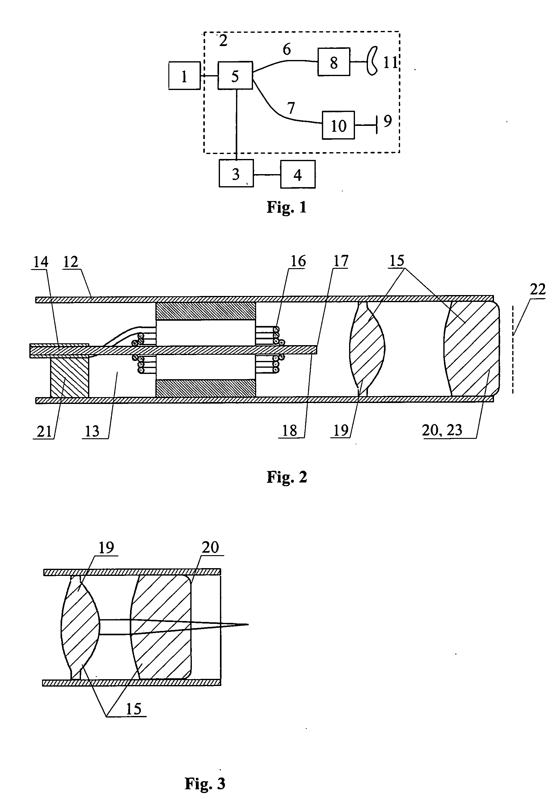
[0076] The developed method for imaging an object, an apparatus for carrying out this method, and a device for delivering low coherence optical radiation are exemplified by an optical fiber interferometer incorporated into an optical low coherence tomography device, and an optical fiber probe, although it is obvious that they can be realized by means of optical elements with lumped parameters.

[0077] The operation of the developed apparatus for imaging an object and of the device for delivering low coherence optical radiation, designed in a specific embodiment as an optical fiber probe, will be best understood from the following description of carrying out the method for imaging an object.

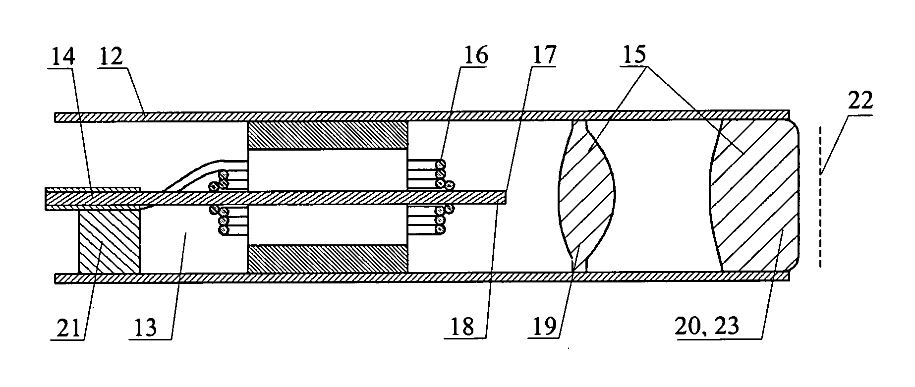
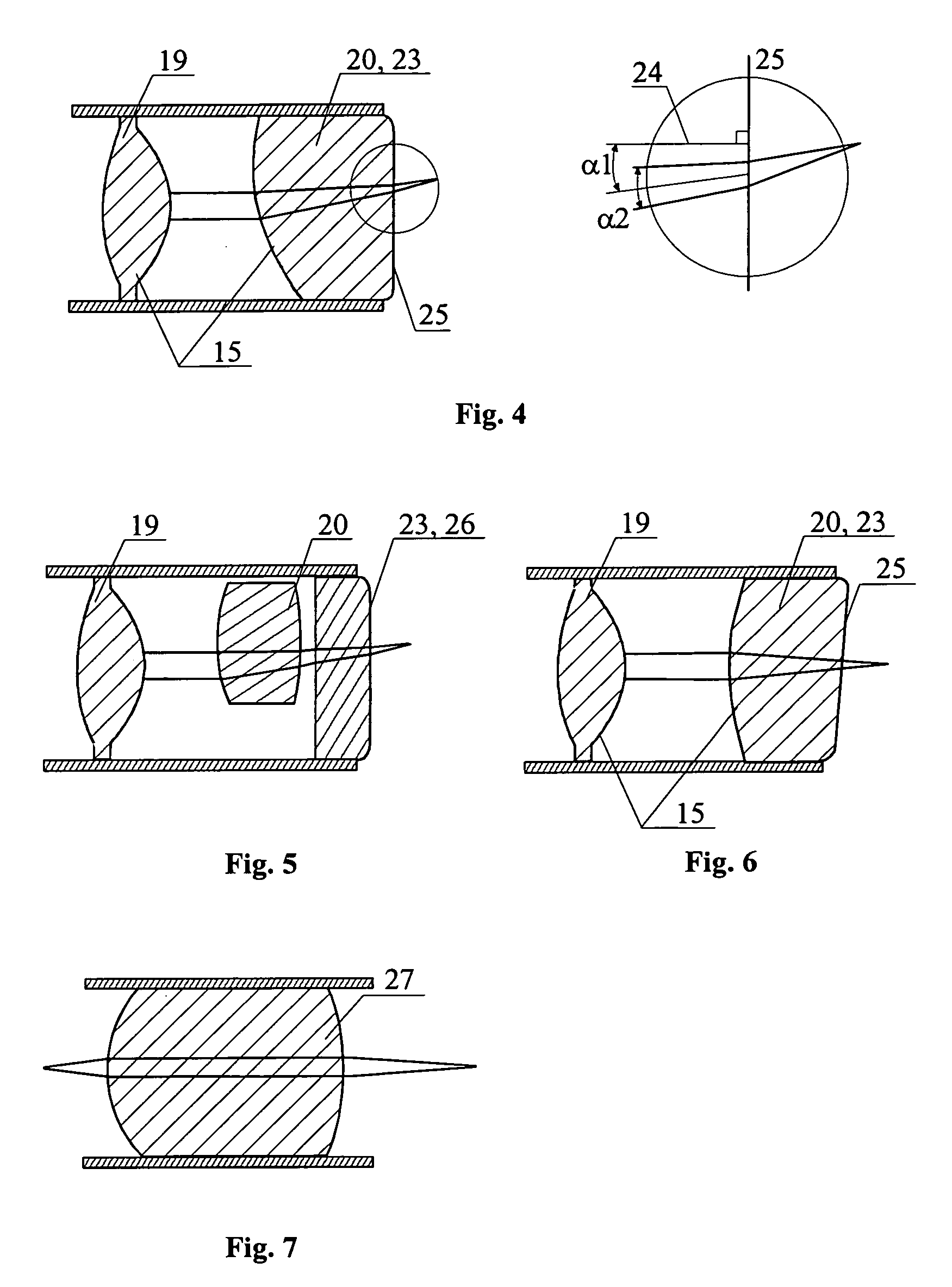
[0078] The method for imaging an object is carried out the following way with the aid of the apparatus of the invention, as depicted in FIG. 1, and with the aid of the optical fiber probe shown in FIG. 2, whose particular embodiments of the optical system are presented in FIG. 3, FIG. 4, FIG. 5, F...


PUM


Abstract

The invention relates to studies of internal structures of objects with the aid of optical means. According to the invention an optical system (15) of the delivering device for low coherence optical radiation, in a particular embodiment, an optical fiber probe (8), includes at least two lens components (19), (20), which have a positive focal power and are positioned substantionally confocally. This ensures a constant propagation time for the low coherence optical radiation propagating from a given point of the transverse scanning surface (28) or (39) to a corresponding conjugate point of the image plane (22). That provides elimination of the transverse scanning related aberration of the optical path length for low coherence optical radiation directed towards the object (11) both for a flat transverse scanning surface (28) and for a transverse scanning surface (39) having a curvature. In another embodiment, together with the substantionally confocal arrangement of lens components (19), (20), the longitudinal scanning is performed by varying the optical path length for the low coherence optical radiation propagating from the transverse scanning surface (28) to the optical system (15), i.e., from the end face (17) of the distal part (18) of the optical fiber (14) to the optical system (15). To achieve this, a device for longitudinal scanning (10) is incorporated into the optical fiber probe (8). This ensures a corresponding shift of the focusing position of the low coherence optical radiation during longitudinal scanning, i.e., allows for alignment of the focusing position of the low coherence optical radiation with the position of the coherence gate and, consequently, their simultaneous movement.

Description

TECHNICAL FIELD [0001] The present invention relates to physical engineering, in particular, to studies of internal structures of objects with the aid of optical means, and can be applied for obtaining an image of an object using low coherence optical radiation in medical diagnostics of individual organs and systems of human body in vivo or in vitro, as well as in industrial diagnostics such as control of technological processes. BACKBROUND ART [0002] Apparatus for imaging an object using low coherence optical radiation are fairly well known. Such apparatus comprise a low coherence light source optically coupled with an optical interferometer and a photodetector, which is connected with a data processing and displaying unit. The optical interferometer is typically designed either as a Michelson optical fiber interferometer or as a Mach-Zender optical fiber interferometer. Regardless of the specific design used, an optical interferometer typically comprises one or two beam splitters,...

Claims


Application Information

Patent Timeline
IPC IPC(8): G02B6/32A61B1/00A61B5/00A61B10/00G01B9/02G01B11/24G01N21/17G01N21/47G02B9/06G02B23/24G02B23/26G02B26/08
CPCA61B5/0066A61B5/0068A61B5/0084A61B5/6852G01N21/4795G02B9/06G02B17/0856G01B9/02002G01B9/0205G01B9/0209G01B9/02063G01B2290/65G02B23/2407
Inventor GELIKONOV, GRIGORY VALENTINOVICHGELIKONOV, VALENTIN MIKHAILOVICHMYAKOV, ALEXEY VICTOROVICHFELDCHTEIN, FELIX ISAAKOVICH
Owner IMALUX CORP
Why Eureka
Try Eureka