Apparatus and method for forming a joint between adjacent members
a joint and adjacent member technology, applied in the direction of forming apparatus, manufacturing tools, couplings, etc., can solve the problems of requiring heavy equipment frames that can impose access limitations, affecting the joint area, so as to reduce the clamping force requirements, promote material flow and deformation, and increase the joint strength
- Summary
- Abstract
- Description
- Claims
- Application Information
AI Technical Summary
Benefits of technology
Problems solved by technology
Method used
Image

Examples
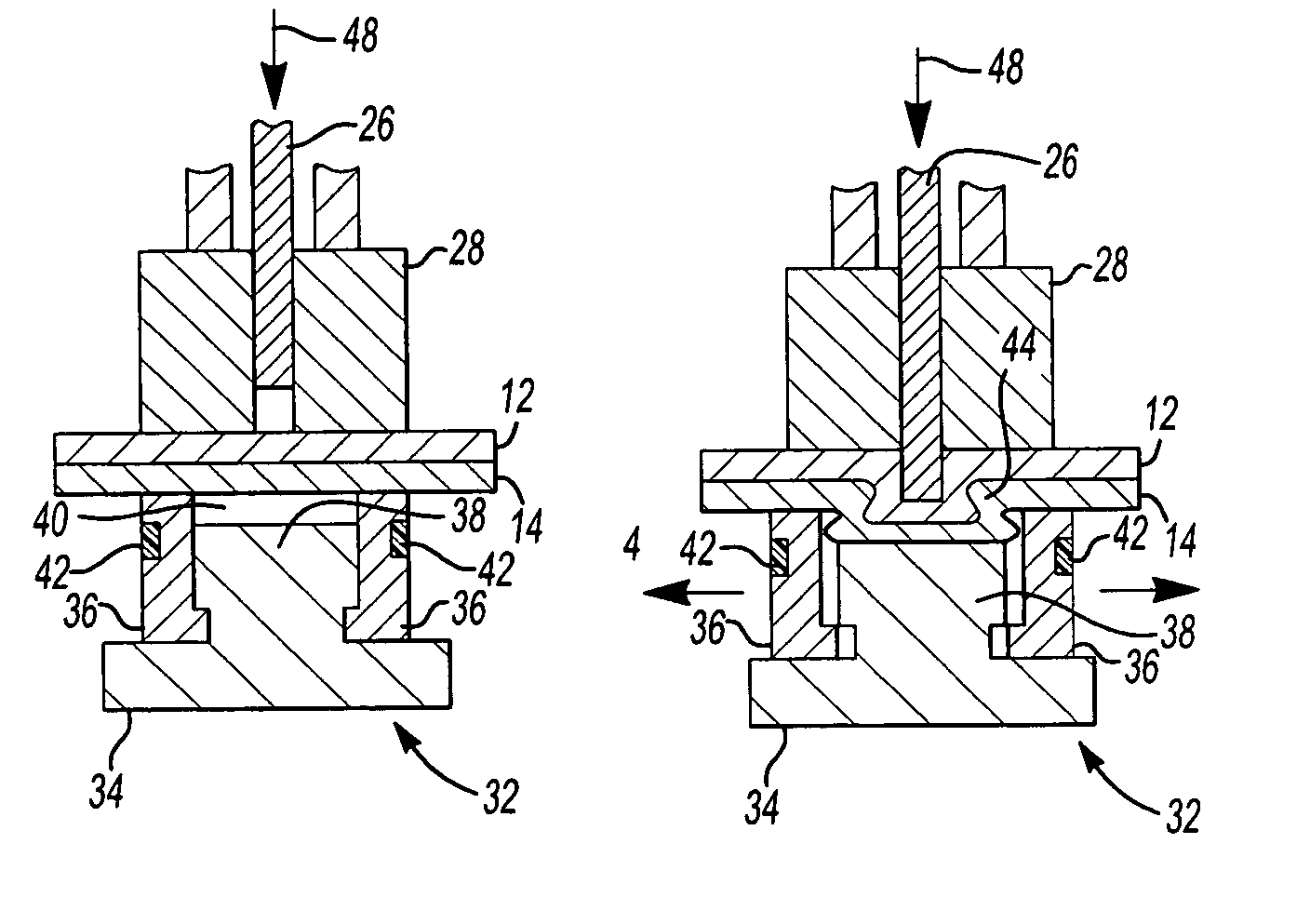
second embodiment
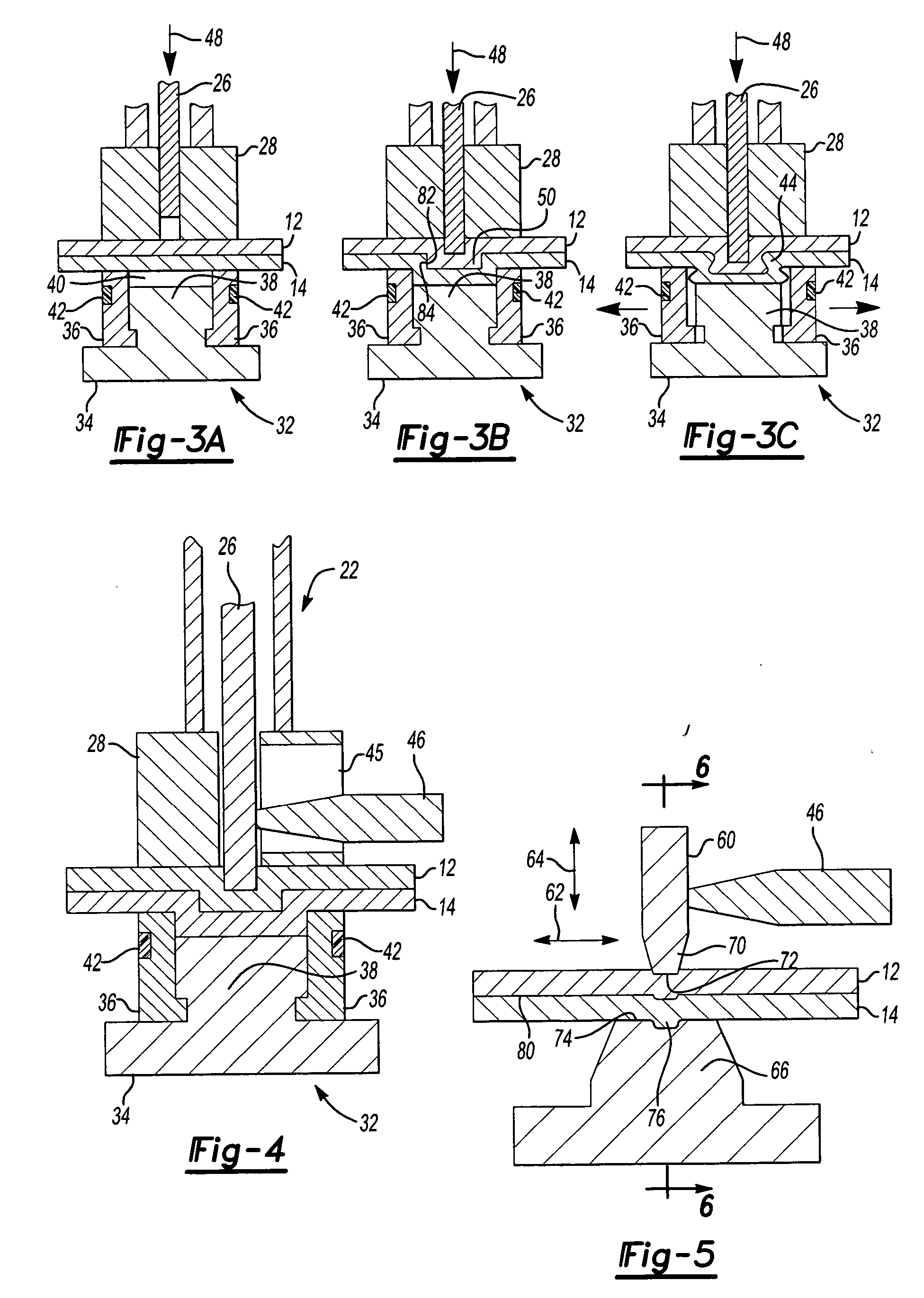
[0033]FIG. 4 illustrates the present invention wherein the transducer 46 is secured to the punch 26 such that energy from the transducer 46 causes the punch 26 to vibrate in the lateral direction, that is, a direction transverse to the longitudinal axis 30 of the punch 26. The transducer 46 extends through an elongated longitudinal slot 45 located in the blank holder 28 and is connected to the punch 26. As set forth above, the punch 26 may impart vibrational energy at any time during the clinching operation. In addition, since the vibrational energy or ultrasonic vibrations are applied or imparted in a transverse direction, they act to impart a solid-state weld to the first and second members or sheets of material 12, 14 placed in an overlapping relationship between the punch assembly 22 and the die assembly 32 through the ultrasonic welding process as ultrasonic metal welding requires relative movement between the first and second members.
[0034] Accordingly, the joint strength from...
third embodiment
[0035] Turning now to FIGS. 5-6, there is shown the present invention for joining first and second members or multiple layers of material wherein the combination of the clinching and ultrasonic welding processes calls for a modification to the geometry of the sonotrode and / or the anvil used in a conventional ultrasonic metal welding operation. A typical ultrasonic welding apparatus includes a sonotrode 60 mounted for movement in a side-to-side or horizontal direction of vibration, shown by the arrow 62. The sonotrode 60 also moves in a vertical manner, shown by the arrow 64, and in cooperation with an anvil 66 clamps the first and second members or sheets of material 12, 14 together in an overlapping, multi-layer relationship. As with the previous embodiments, the transducer 46 operates to transfer high frequency vibrations from the transducer 46 to the sonotrode 60 to impart vibrational energy to the first and second members or sheets of material 12, 14. The high frequency vibratio...
PUM
| Property | Measurement | Unit |
|---|---|---|
| Force | aaaaa | aaaaa |
| Pressure | aaaaa | aaaaa |
| Mass | aaaaa | aaaaa |
Abstract
Description
Claims
Application Information
 - Generate Ideas
- Intellectual Property
- Life Sciences
- Materials
- Tech Scout
- Unparalleled Data Quality
- Higher Quality Content
- 60% Fewer Hallucinations
Browse by: Latest US Patents, China's latest patents, Technical Efficacy Thesaurus, Application Domain, Technology Topic, Popular Technical Reports.
© 2025 PatSnap. All rights reserved.Legal|Privacy policy|Modern Slavery Act Transparency Statement|Sitemap|About US| Contact US: help@patsnap.com