Blade for rotary cutting machine

a cutting machine and blade technology, applied in the field of blades for rotary cutting machines, can solve the problems of unsightly brown edges, inconvenient maintenance of cutting edges in rotary cutting machines, and inability to meet the needs of maintenance, so as to minimize any flexing, enhance vegetation growth, and improve performance

Inactive Publication Date: 2006-08-03
HILL ROBERT G JR
View PDF51 Cites 47 Cited by
  • Summary
  • Abstract
  • Description
  • Claims
  • Application Information

AI Technical Summary

Benefits of technology

[0016] One or more stiffening ribs can be added to either the blade assembly or the integral blade to improve performance in heavier duty applications. As either the blade assembly or the integral blade rotates during operation, an imbalance or stress due to impacting vegetation can cause the elongated blade to flex. The addition of a stiffening rib will minimize any flexing that might occur. Too much flexing will generate vibration and cause additional wear on the rotary cutting machine and on the elongated blade.
[0017] One or more mulching blades can be added to either the blade assembly or to the integral blade to re-cut the vegetation that has been cut by the front facing edge. Mulching blades protrude above the top surface of the elongated blade at an angle greater than 20 degrees. The advantage to incorporating the mulching blades on either the blade assembly or the integral blade is that there is no need to collect the cut vegetation to achieve a cleanly cut appearance that is desirable in many applications wherein a rotary cutting machine is used. As the vegetation is re-cut into small pieces, it is evenly dispersed over the area being cut which further enhances vegetation growth as the cut vegetation decays.
[0018] In order to enhance the performance of the blade assembly or the integral blade, the trailing edge of the insert end or of the cutting end, respectively, forms a lift surface with the top surface that causes air flow which lifts the vegetation into the path of the rotating front facing edge. The lift surface acts as a fan blade drawing air from the area of the vegetation which creates a vacuum effect on the vegetation making it stand up to be cut by the rotating blade assembly or integral blade. The result is uniformly cut vegetation such as grass in a lawn where each blade of grass has the appearance of being cut uniformly.
[0019] The leading edge of the insert end on the blade assembly and the cutting edge on the integral blade are formed at a skew angle with the longitudinal axis. The skew angle changes the angle of attack for the front facing edge of the replaceable insert and the integral blade during operation. The skew angle adds a slicing action to any cutting edge and enhances the slicing action of the geometrically shaped fingers described above. The skew angle causes one section along the cutting edge to engage...

Problems solved by technology

Maintaining sharp cutting edges in a rotary cutting machine is currently a time consuming and inefficient process that usually requires the removal of the entire blade from the mower.
In both home and commercial mowing applications, the maintenance of a sharp cutting edge is very important due to the demand for a fast and aesthetically pleasing final cut which can be a major cost of operation.
Dull blades cause the vegetation being cut to be broken off as opposed to being cut which effects the efficient operation of the mower and produces an unevenly and ununiformly cut lawn that frequently results in unsightly brown edges.
Problems can be encountered if the cutting edge is incorrectly sharpened.
The cutting properties, balance, and hardness of the cutting edge, and safety could be dramatically affected by an improperly sharpened cutting edge.
The typical end result of sharpening a case hardened blade is that the hardened surface of the cutting edge is removed, exposing softer metal that dulls more quickly than the original hardened surface, and the balance of the blade is ...

Method used


Image

  • Blade for rotary cutting machine
  • Blade for rotary cutting machine
  • Blade for rotary cutting machine

Examples


Embodiment Construction

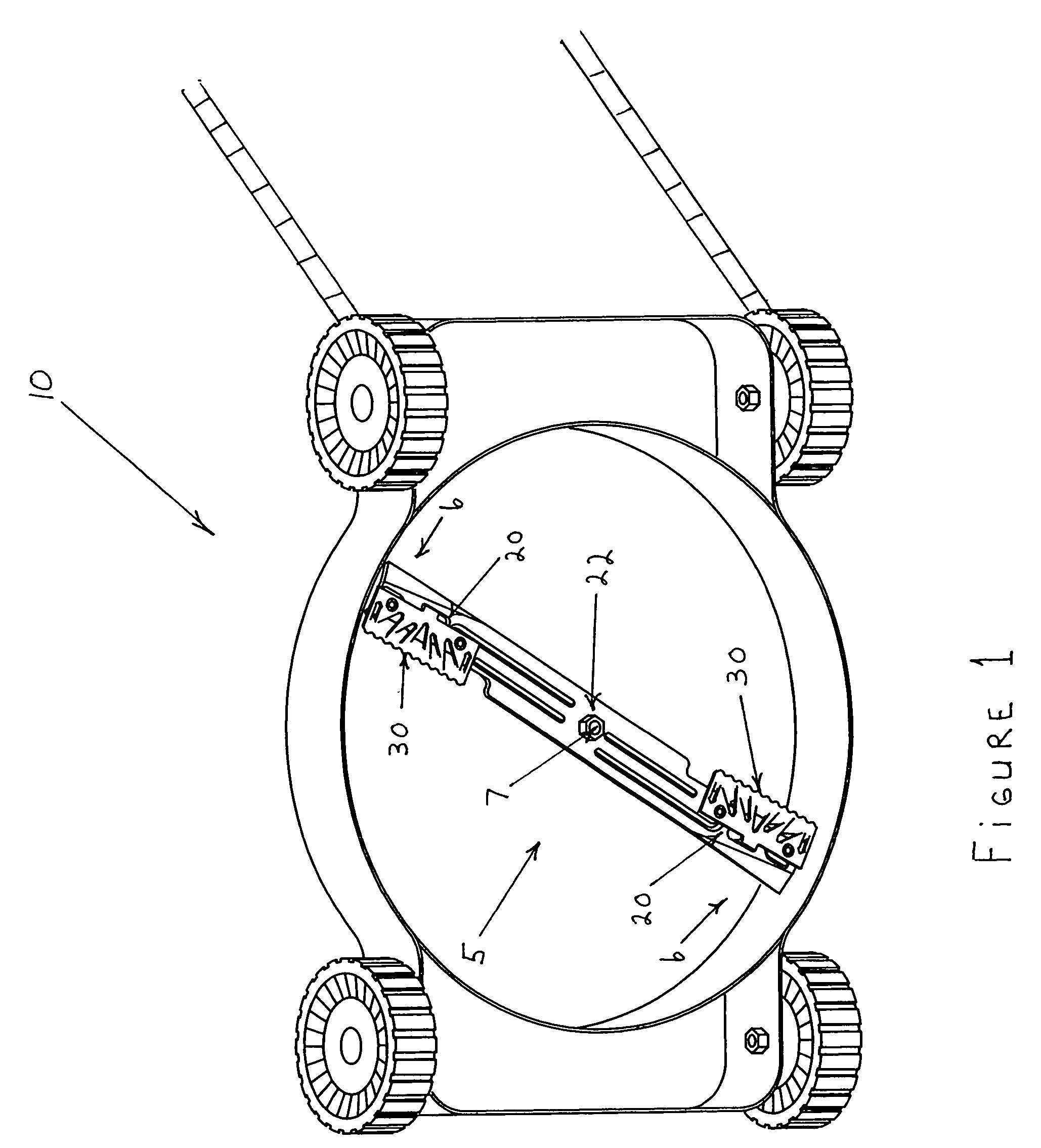
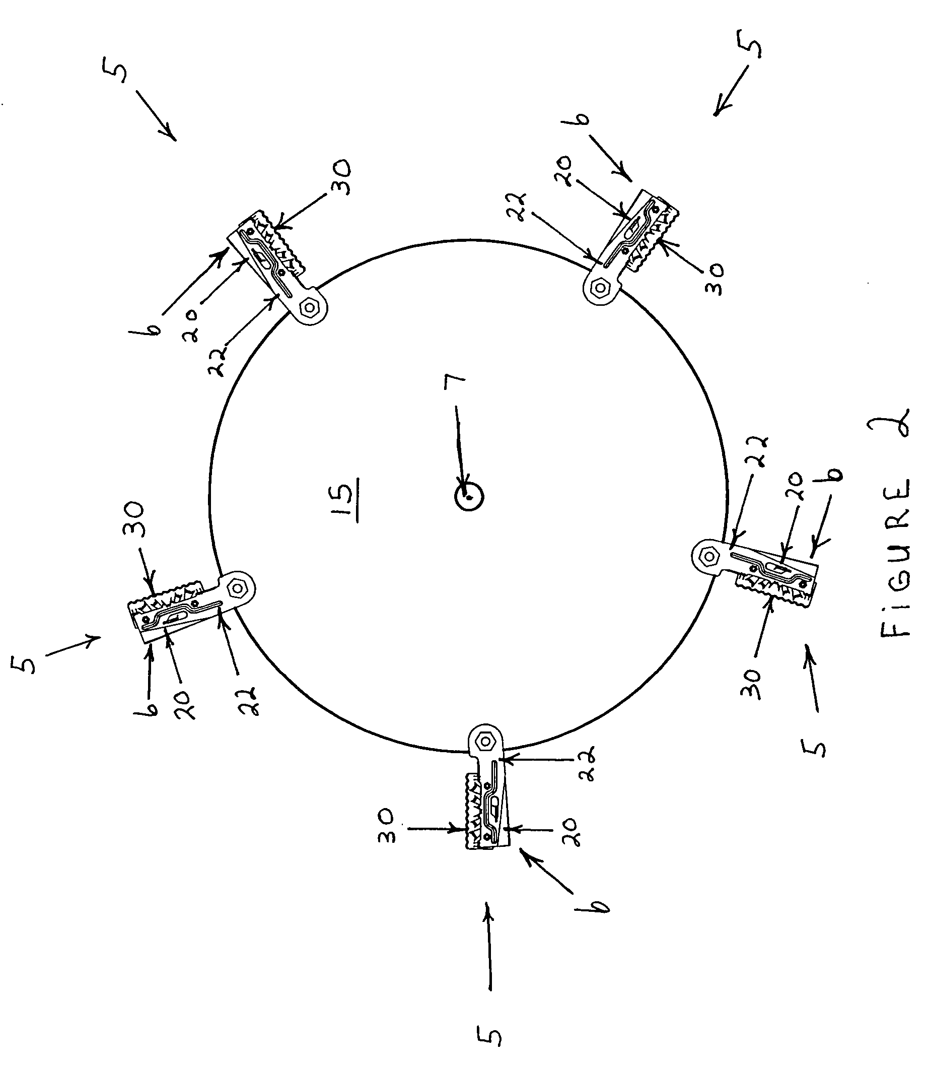
[0043] Referring now to the drawings wherein like reference numerals have been used throughout to designate like parts among the several views. Referring to FIG. 1 which shows a perspective view of the bottom of a rotary cutting machine 10 having a blade assembly 5 with an insert holder 20 located at each blade end 6 of elongated blade 22 each with a replaceable insert 30 that rotates about a central axis 7. In FIG. 2, blade platform 15 is shown with multiple blade assemblies 5, each having an elongated blade 22 with a single insert holder 20 and a replaceable insert 30 located at only one blade end 6 spaced around the circumference of blade platform 15 configured to rotate about central axis 7.

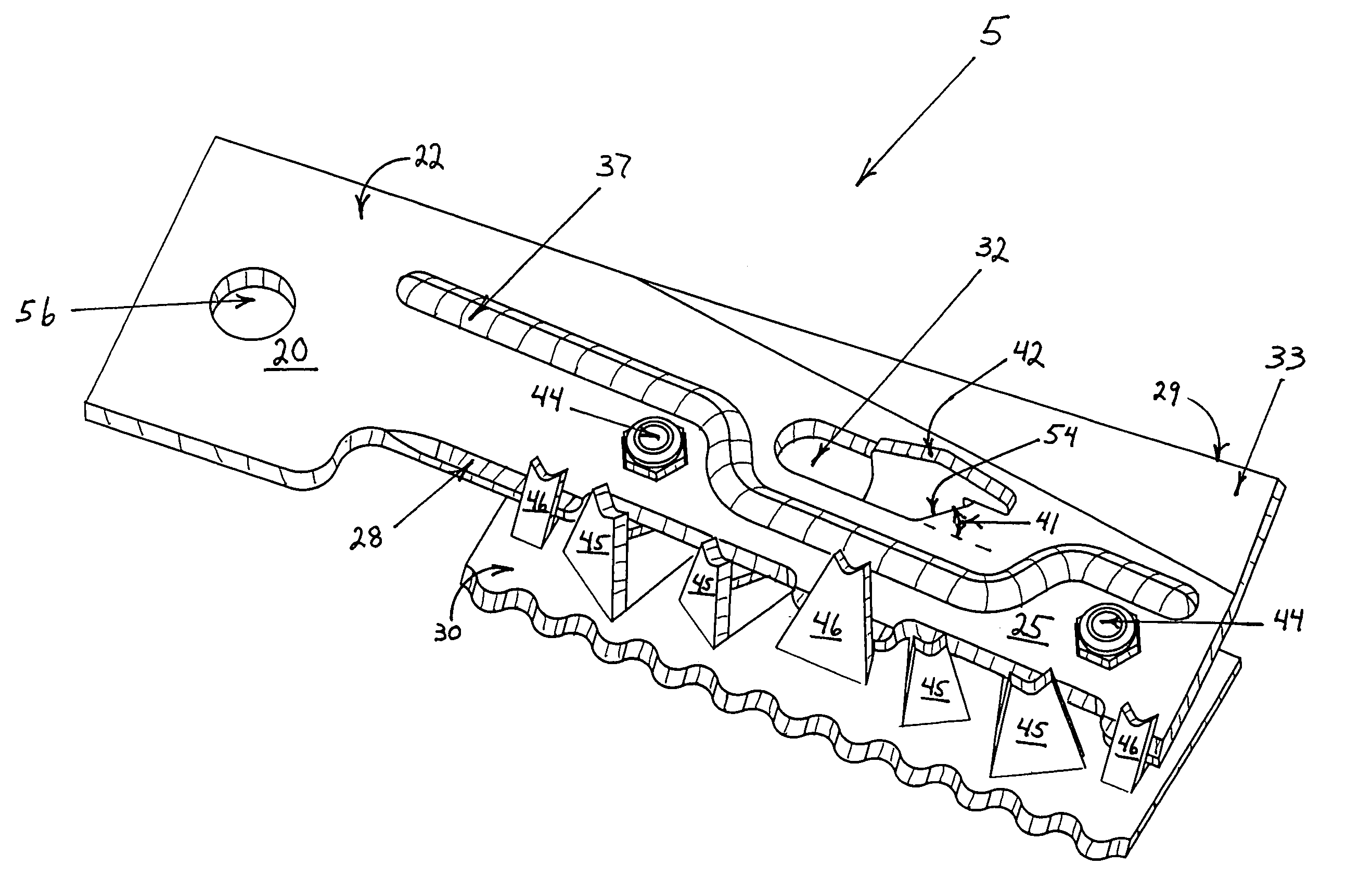
[0044]FIG. 3 is a perspective view of insert holder 20 prior to the installation of replaceable inserts 30 (not shown). Insert holder 20 consists of an elongated blade 22 that rotates about central axis 7. Longitudinal axis 24 extends beyond the length of insert holder 20 to define relative ...


PUM


Abstract

A blade with an easily and economically maintainable cutting edge for cutting vegetation in a rotary cutting machine such as in a lawnmower or brush cutter is described. A blade assembly is comprised of an elongated blade with replaceable inserts that enhance the cutting and mulching functions of the rotary cutting machine. The replaceable inserts are installed at a skew angle and provide an easily maintainable cutting edge that has geometrically shaped fingers that provide both a chopping and a slicing action that enhances the cutting performance of the blade assembly. Mulching blades re-cut the vegetation severed by the shaped fingers into smaller pieces before the vegetation exits the rotary cutting machine to minimize or eliminate the need to pick up the cut vegetation while maintaining an aesthetically pleasing final cut. Each replaceable insert has a safety connector that prevents the dislodging of the replaceable insert from the blade assembly during operation in the event that fasteners fail during operation. An integral blade is also anticipated that has geometrically shaped fingers installed at a skew angle that provide both a chopping and a slicing action.

Description

BACKGROUND OF THE INVENTION [0001] 1. Field of the Invention [0002] This invention relates, in general, to blades for rotary cutting machines such as those used to maintain lawns and to cut various types of vegetation found in yards and fields. The ease with which the sharpness of the blade can be maintained is determined by the effort required to replace or remove the blade for sharpening. A cutting edge that provides both a chopping and slicing action while cutting the vegetation ensures a cleaner and more accurate cut. A blade that provides quick and economic maintenance of a sharp cutting edge in a rotary cutting machine with superior performance is provided in the present invention. [0003] 2. Description of the Prior Art [0004] Maintaining sharp cutting edges in a rotary cutting machine is currently a time consuming and inefficient process that usually requires the removal of the entire blade from the mower. In both home and commercial mowing applications, the maintenance of a ...

Claims


Application Information

Patent Timeline
IPC IPC(8): A01D34/73
CPCA01D34/73
Inventor HILL, ROBERT G. JR.
Owner HILL ROBERT G JR
Why Eureka
Try Eureka