Piezoelectric vibration element, piezoelectric vibrator, piezoelectric oscillator, frequency stabilization method, and method of manufacturing the piezoelectric vibrator

a technology of piezoelectric vibrators and vibration elements, which is applied in the direction of generators/motors, device details, device material selection, etc., can solve the problems of increasing the frequency of generators, affecting the quality of the piezoelectric vibrator, etc., and achieves the effect of superior impact resistan

Active Publication Date: 2006-08-03
SEIKO EPSON CORP
View PDF6 Cites 22 Cited by
  • Summary
  • Abstract
  • Description
  • Claims
  • Application Information

AI Technical Summary

Benefits of technology

[0039] The silicon based conductive adhesive having a superior impact resistance property is very effective to fix the piezoelectric vibration element within the insulating case. And when the silicon vapor component emitted from the silicon based conductive adhesive when the insulating case is hermetically encapsulated is attached and deposited on the metal layer of the piezoelectric vibration element, the resonant frequency decreases below the final target frequency over time, which becomes the cause of mis-operation of an apparatus on which the piezoelectric device is loaded. According to the invention, it is possible to provide the piezoelectric vibration element, the piezoelectric vibrator, the piezoelectric oscillator, the frequency stabilization method, and the method of manufacturing the piezoelectric vibrator, which may form a layer formed of silicon molecules on a metal layer to saturate the amount of molecular absorption in a very short time ranging from several seconds to several minutes by low-cost apparatus and method using simple equipment and order, so that the decrease of the resonant frequency may be stopped to be stabilized, and the decrease of the productivity may not occur.

Problems solved by technology

In addition, it was confirmed that the tendency of the frequency decrease becomes severe after a reflow process for loading the piezoelectric device on the printed board by the assembly maker.
Various inferences are drawn about the cause of these phenomena, however, an explicit cause is not found so that the fundamental solution cannot be obtained, which is the actual circumstance.
However, according to this related art, many problems occur as follows.
That is, a warpage occurs due to a temperature change to cause the temperature characteristic to be degraded.
Accordingly, the solution proposed by the above-described publication is not enough.
And when the silicon vapor component emitted from the silicon based conductive adhesive when the insulating case is hermetically encapsulated is attached and deposited on the metal layer of the piezoelectric vibration element, the resonant frequency decreases below the final target frequency over time, which becomes the cause of mis-operation of an apparatus on which the piezoelectric device is loaded.

Method used


Image

  • Piezoelectric vibration element, piezoelectric vibrator, piezoelectric oscillator, frequency stabilization method, and method of manufacturing the piezoelectric vibrator
  • Piezoelectric vibration element, piezoelectric vibrator, piezoelectric oscillator, frequency stabilization method, and method of manufacturing the piezoelectric vibrator
  • Piezoelectric vibration element, piezoelectric vibrator, piezoelectric oscillator, frequency stabilization method, and method of manufacturing the piezoelectric vibrator

Examples


first embodiment

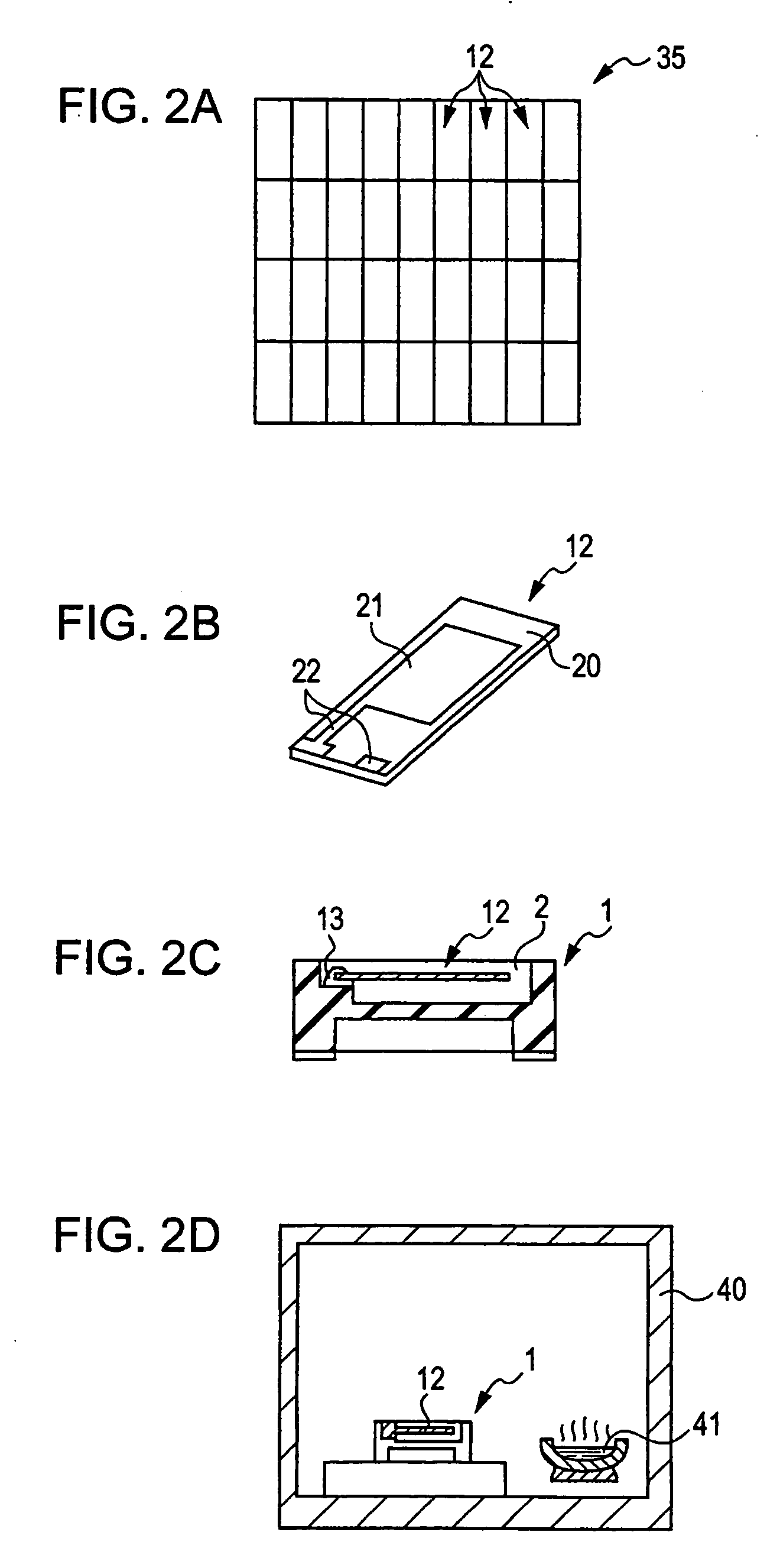
[0064] According to the invention for coping with such defects, there is provided a method of stabilizing the frequency in advance by means of heating before getting a piezoelectric device on the market. That is, according to this method, the piezoelectric device is subject to heating for 70 hours or more at a temperature lower than a silicon pyrolysis temperature, for example, at 230° C. among temperatures higher than the room temperature, preferably among temperatures exceeding the boiling point of the silicon molecule (e.g., 188° C. at D3) while encapsulating the piezoelectric device, so that silicon vapor may be positively emitted from the silicon adhesive within the hermetically encapsulated insulating case, which thus allows the amount of absorbing the silicon molecule into the surface of the exciting electrode layer in a unit time to be increased by increasing the concentration of the silicon vapor for a short time as compared to a case of natural aging. As a result, the time...

second embodiment

[0075] Next, according to the invention, a technique of accelerating the silicon molecular absorption is provided instead of heating, which makes the frequency of the crystal oscillation element reach the frequency stabilization region for a short time.

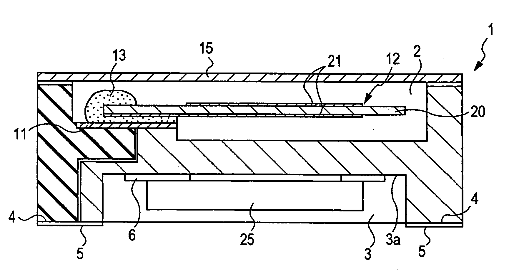
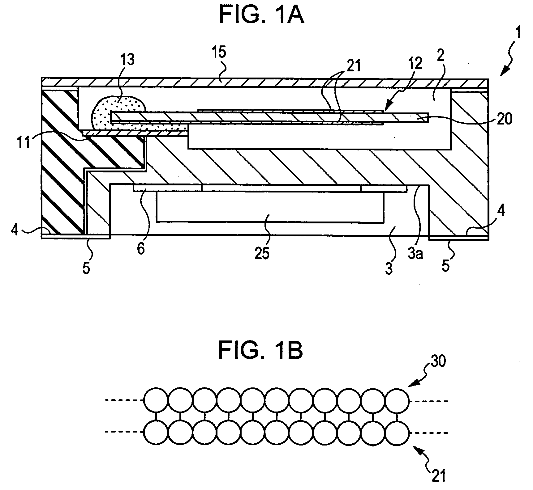
[0076] That is, in the present embodiment, the monomolecular layer 30 of the silicon molecule is formed in advance to cover the entire surface of the exciting electrode layer 21 by exposing the exciting electrode layer 21 to an atmosphere of the silicon vapor prepared in advance before encapsulating the insulating case 1. According to this structure, a long term heating process for making the concave portion 2 of the insulating case 1 subject to the atmosphere of silicon vapor, which has been required in the first embodiment, is not necessary, so that the resonant frequency of the crystal oscillation element may be reduced to a predetermined target value (target frequency) at one time from the set value at the time of frequency adjust...


PUM

PropertyMeasurementUnit
temperatureaaaaaaaaaa
timeaaaaaaaaaa
boiling pointaaaaaaaaaa

Abstract

A piezoelectric vibration element is provided which includes a piezoelectric substrate formed of a thickness slip based piezoelectric material and a metal layer formed on a surface of the piezoelectric substrate. In the piezoelectric vibration element, a surface of the metal layer is covered by a layer formed by chemical absorption with a material having a nonbonding electron pair.

Description

BACKGROUND [0001] 1. Technical Field [0002] The present invention relates to a piezoelectric vibration element capable of effectively preventing, without decreasing the productivity, defects that a resonant frequency of the hermetically encapsulated piezoelectric vibration element fixed within an insulating case by a silicon-based conductive adhesive is degraded over time, a piezoelectric vibrator, a piezoelectric oscillator, a frequency stabilization method, and a method of manufacturing the piezoelectric vibrator. [0003] 2. Related Art [0004] A surface-mounted type piezoelectric device such as a crystal oscillator having a structure that the piezoelectric vibration element is hermetically encapsulated within the insulating case, is used as a reference frequency generation source, a filter or the like in an electronic apparatus like a computer or a communication apparatus like a cellular phone, a pager or the like. And miniaturization is also required on the piezoelectric device in...

Claims


Application Information

Patent Timeline
Patent Type & Authority Applications(United States)
IPC IPC(8): H01L41/08H01L41/09H01L41/18H01L41/22H01L41/23H01L41/253H01L41/311H01L41/313H03B5/32H03H3/02H03H9/19
CPCH03H3/04H03H9/02149H03H9/0552H03H9/1021H03H9/17Y10T29/49155Y10T29/49146Y10T428/2809Y10T29/42Y10T29/49004H03H2003/0478H10N30/80H10N30/87
Inventor OHSHIMA, TSUYOSHIHASEGAWA, SHINWATANABE, NORIYUKI
Owner SEIKO EPSON CORP
Why Eureka
Try Eureka