High performance microreaction device

a micro-reaction device, high-performance technology, applied in indirect heat exchangers, laboratory glassware, lighting and heating apparatus, etc., can solve the problems of inability to clean, difficult disassembly and cleaning, and difficulty in cleaning, etc., to achieve fast mixing performance, low pressure drop performance, and fast mixing performance

Inactive Publication Date: 2006-08-03
CORNING INC
View PDF4 Cites 38 Cited by
  • Summary
  • Abstract
  • Description
  • Claims
  • Application Information

AI Technical Summary

Benefits of technology

[0021] As a result these and other features, the inventive device can and preferably does provide heat exchange capability of at least 20 watts, or more preferably of at least 40 watts from a reactant stream flowing at 20 ml/min, and a total dwell-time of at least 6-10 seconds at that 20 ml/min flow rate (corresponding to a dwell-time passage volume of 2 to about 3.33 ml), with at least 90% fast mixing performance at flow rates from at least as low as 20 ml/min and up. Further, the inventive device can and preferably does provide low pressure drop of less than about 2 bar, desirably even less than about 1 bar, at flow rates as high as about 100 ml/min or even more. Surprisingly, embodiments of the inventive dev

Problems solved by technology

In chemical process technology, throughput is often an important issue, and for this reason micro mixer designs going beyond the concept of two streams merging in a single channel are needed.
The finely divided, highly parallel structures which are the subject of such efforts do offer potential advantages, such as the possibility of very fast mixing with very low pressure drop in mixers, and of very fast, very high heat exchange rates in heat exchangers, effectively providing for increased throughput by internal “numbering up.” Yet such very fine structures can also be particularly prone to clogging or fouling in the presence of particulates or film-forming materials, and once clogged or fouled, such structures may be irreparable, or

Method used


Image

  • High performance microreaction device
  • High performance microreaction device
  • High performance microreaction device

Examples


examples

[0066] A testing method used to quantify mixing quality of two miscible liquids is described in Villermaux J., et al. “Use of Parallel Competing Reactions to Characterize Micro Mixing Efficiency,” AlChE Symp. Ser. 88 (1991) 6, p. 286. For testing generally as described herein, the process was to prepare, at room temperature, a solution of acid chloride and a solution of potassium acetate mixed with KI (Potassium Iodide). Both of these fluids or reactants were then continuously injected by means of a syringe pump or peristaltic pump into the micromixer or microreactor to be tested.

[0067] The resulting test reaction results in two competing reactions of different speeds—a “fast” reaction that produces a UV absorbing end product, and an “ultrafast” one that dominates under ultrafast mixing conditions, producing a transparent solution. Mixing performance is thus correlated to UV transmission, with theoretically perfect or 100% fast mixing yielding 100% UV transmission in the resulting ...

performance example i

Mixing Performance, Pressure Drop and Dwell Time

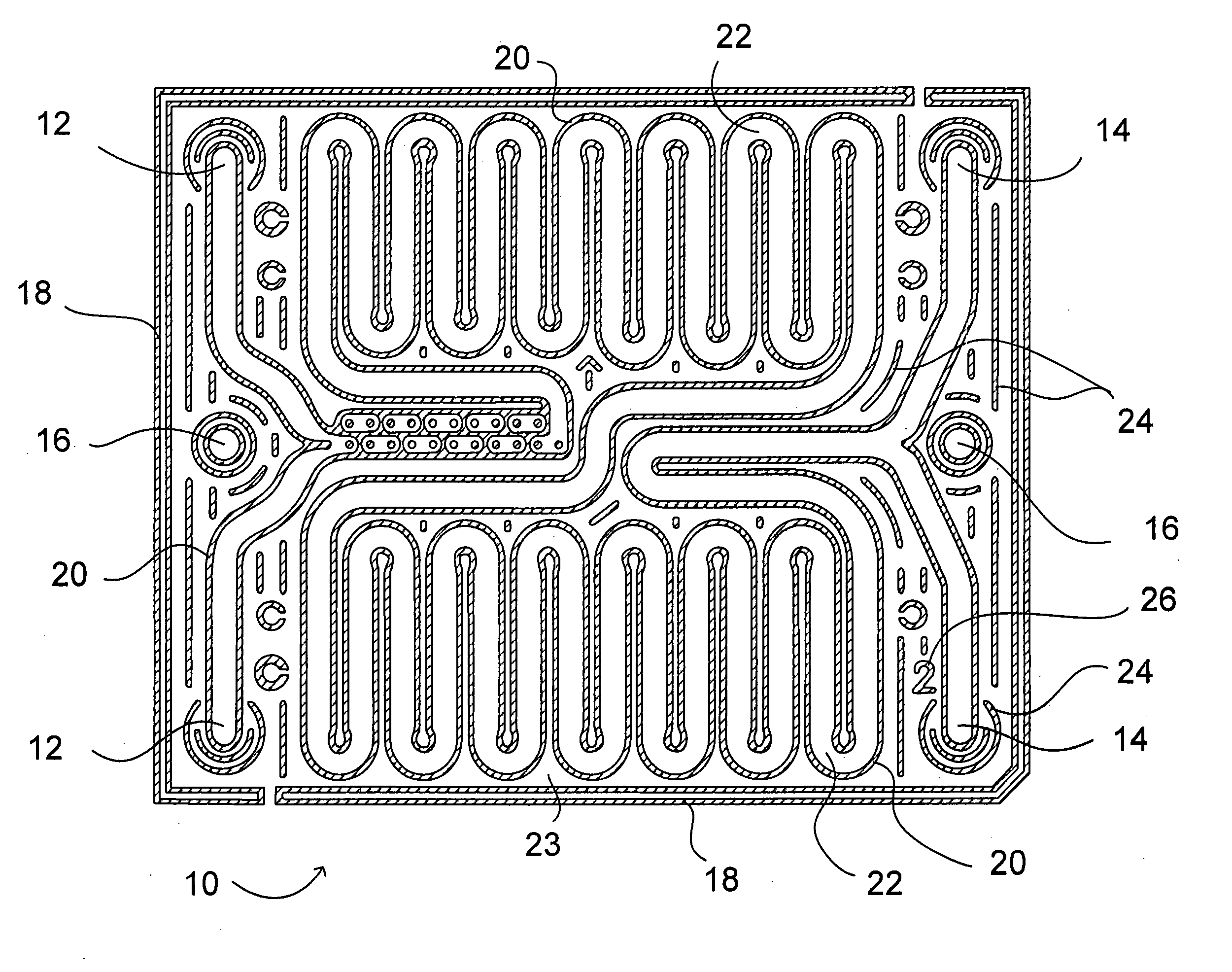
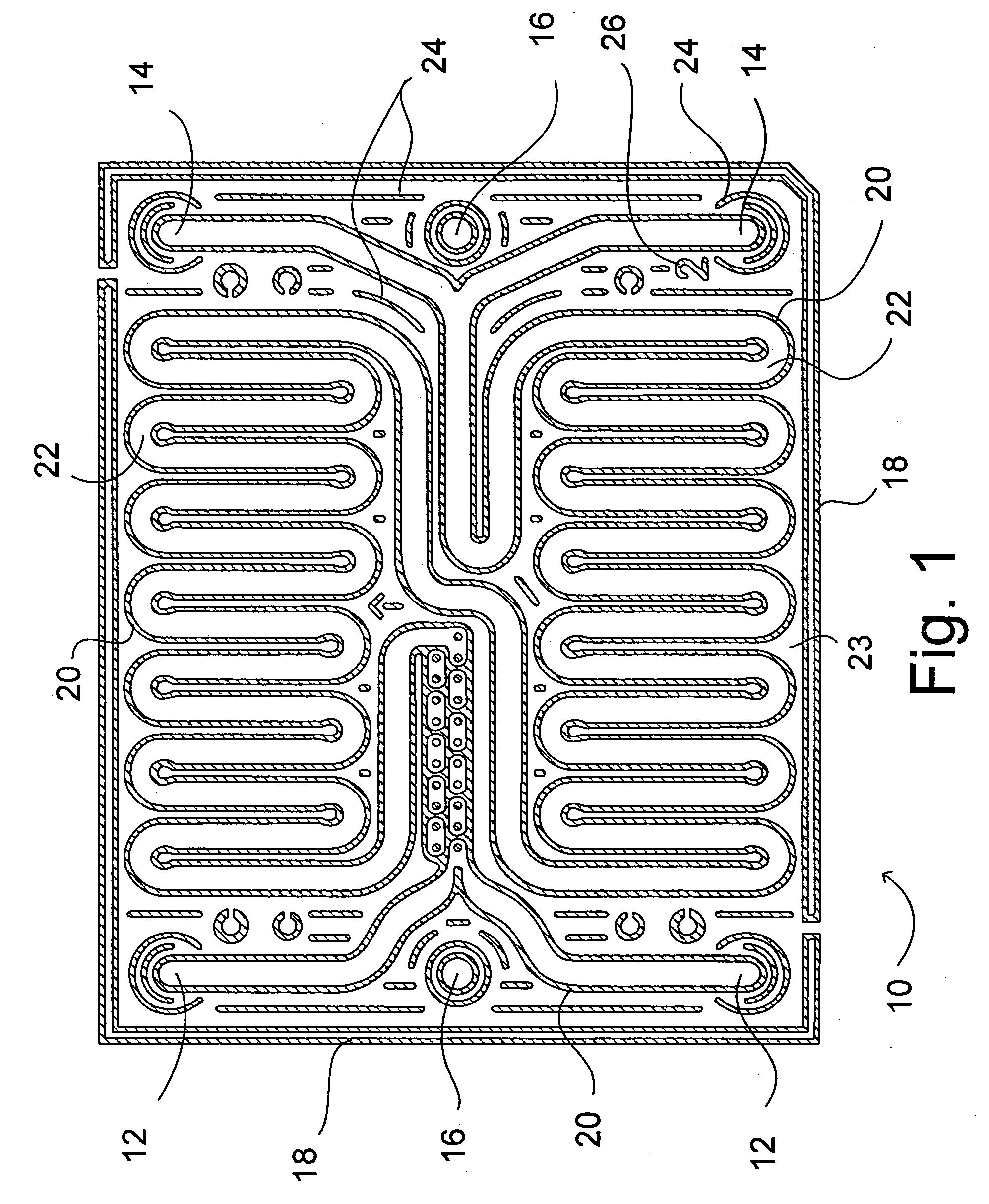
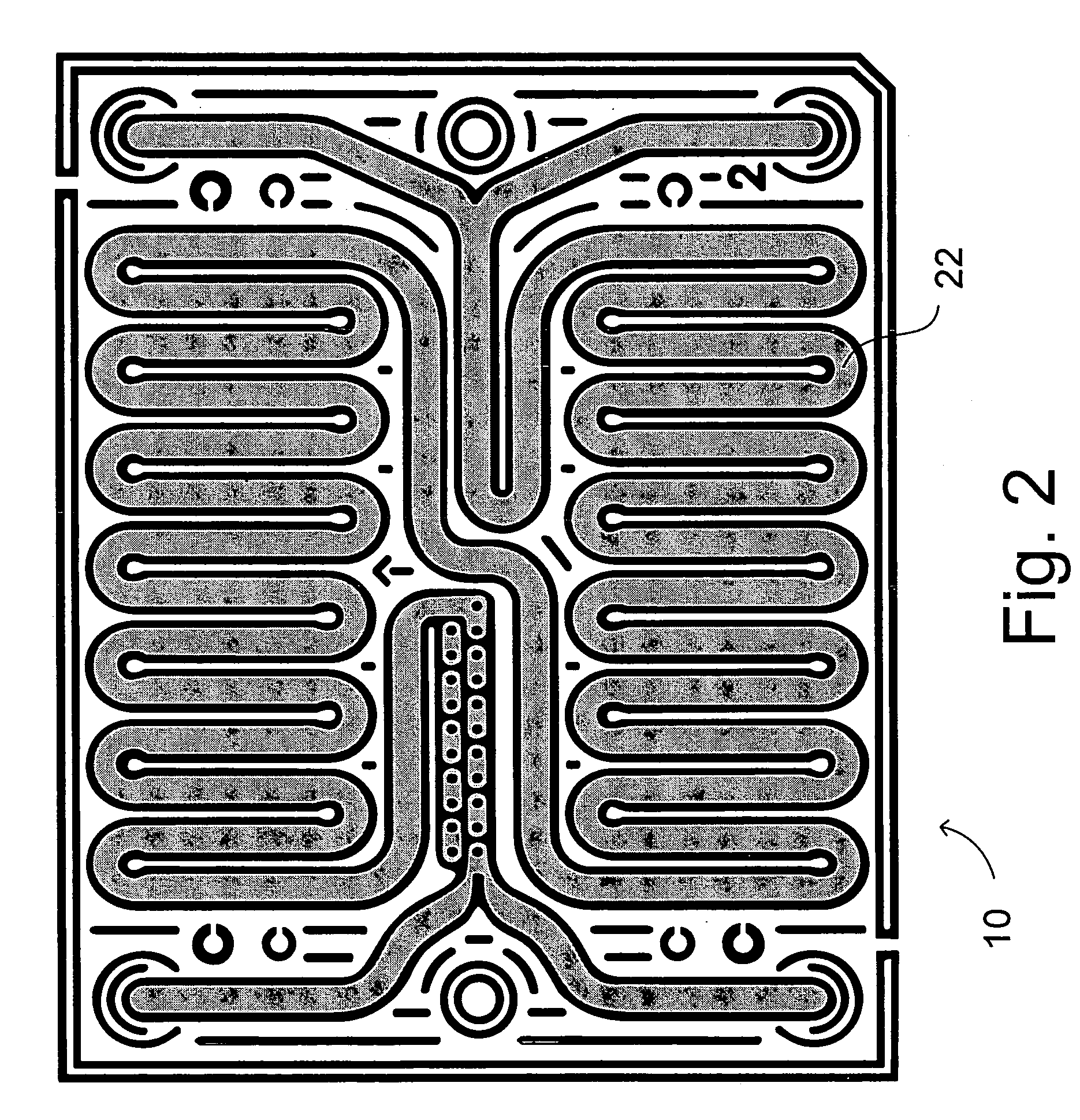
[0070] Mixing tests performed as described above were made on nine different samples of the embodiment of the present invention shown in FIGS. 1-5, 8-10, 12 and 13 above. Average fast mixing performance as a function of flow rate is shown by the data 100 plotted in the graph in FIG. 15, and average pressure drop as a function of flow rate is shown by the data 200 plotted in the graph in FIG. 16. Fast mixing resulting in 90% measured mixing performance or greater is present from a range of flow rates beginning just below 20 ml / min and upward, corresponding to a minimum pressure drop of slightly less than 90 mBar. Residence times or “dwell times” as function of flow rate are plotted as data 300 in FIG. 17.

performance example ii

Repeatability and Durability of Mixing

[0077] Fast mixing tests performed as described above were made at 20 ml per minute flow rate on nine different samples of the embodiment of the present invention shown in FIGS. 1-10, 12 and 13, and the range of values was compared. Transmission percentage results ranged from 93 to 95% at 20 ml / min. flows. Repeatability in the same device was also very good at ±1%.

[0078] Samples of devices according to the present invention, formed in glass according to the process referenced above, were also subjected to alkaline corrosion by flowing 1N (1M) NaOH solution at 95° C. through the reactant passage(s) at 20 ml / min. Pressure drop as a function of flow rate, total internal volume, and mixing performance were tested after 0, 100, 200 and 300 hours of such corrosion. After 300 hours of corrosion, internal volume increased by about 30% and pressure drop was reduced by half. Mixing performance, however, remained essentially stable over the duration of t...


PUM

PropertyMeasurementUnit
Pressureaaaaaaaaaa
Flow rateaaaaaaaaaa
Volumeaaaaaaaaaa

Abstract

A microfluidic device includes a thermal buffer fluid passage and a reactant passage having mixing and dwell time sub-passages all defined within an extended body, the dwell-time sub-passage having at least 1 ml volume, and the mixing sub-passage being in the form of a unitary mixer not requiring precise splitting of flows to provide good mixing. The device is desirably formed in glass or glass-ceramic. The unitary mixer is structured to generate secondary flows in the reactant fluid and is preferably closely thermally coupled to the buffer fluid passage by sharing one or more common walls.

Description

CROSS-REFERENCE TO RELATED APPLICATIONS [0001] This application claims the benefit of priority under 35 U.S.C. § 119 of European Patent Application Serial No. 05290046.1 filed on Jan. 7, 2005. BACKGROUND OF THE INVENTION [0002] 1. Field of the Invention [0003] The present invention relates generally to microreaction devices, defined herein as devices having internal channels or chambers of millimeter to submillimeter dimension for conducting mixing and chemical reactions, and more particularly, to such devices particularly optimized for achieving well controlled continuous operation of exothermic reactions at relatively high throughput rates. [0004] 2. Technical Background [0005] Microreaction technology, broadly understood, involves chemical and biological reaction devices having intentionally structured features, such as flow passages and the like, with one or more dimensions in the millimeter, or typically sub-millimeter or micron scales. [0006] One current focus for such technol...

Claims


Application Information

Patent Timeline
IPC IPC(8): B01J19/00
CPCB01F5/0603B01F5/061B01F5/0643B01F5/0646B01F5/0647B01F5/0655B01F13/0059B01F2005/0621B01F2005/0636B01J19/0093B01J2219/00783B01J2219/00822B01J2219/00824B01J2219/00831B01J2219/00833B01J2219/0086B01J2219/00873B01J2219/00889B01L3/5027F28D9/0043F28D9/0056F28D9/0062F28F2210/10F28F2260/02F28F2250/102B01F25/421B01F25/4317B01F25/4322B01F25/431B01F25/431971B01F25/4338B01F25/4331B01F25/433B01F33/30B01J19/00B01F23/40
Inventor CAZE, PHILIPPEGUERMEUR, CELINE CLAUDENEDELEC, YANN P MTHEMONT, JEAN-PIERREWOEHL, PIERRE
Owner CORNING INC
Why Eureka
Try Eureka