Stent with variable features to optimize support and method of making such stent

a technology of variable features and stents, applied in the field of stents, can solve the problems of plaque breaking off, “flaring out” of the leading edge of the stent, and reducing the chance of a potential trauma point being created in the vessel, so as to achieve good radial support, stability and coverage of the vessel wall

Inactive Publication Date: 2006-08-03
MEDINOL LTD
View PDF37 Cites 23 Cited by
  • Summary
  • Abstract
  • Description
  • Claims
  • Application Information

AI Technical Summary

Benefits of technology

[0006] The present invention provides for various embodiments of an intraluminal stent which includes varied or different mechanical properties along the axial length of the stent in order to improve stent end effects, to accommodate variable vessel features or to comply with the vessel's natural flexing during systolic cycles. As a result, the various embodiments of the present invention allow for variable properties such as flexibility or radial support between axial regions of the stent. These varied properties can be accomplished in a number of different ways, including decreasing or increasing the thickness or width of elements of one or more of the sections relative to other sections and / or increasing or decreasing the axial length of one or more of the sections and / or changing the cell shape and size and / or changing material properties (e.g., strength, elasticity, etc.) of the material in one section relative to other sections.
[0007] The various embodiments of the stents of the present invention may be adapted to provide more flexibility at the ends to allow the stent to accommodate the curvature of a vessel in which the stent is implanted. The degree of flexibility and the distance from the end of the stent to which the extra flexibility is imparted may be varied as specific applications dictate. This flexibility at the ends reduces the chance of a potential trauma point being created in the vessel by the stent tip pressing on the wall outside of the curve if the stent is not flexible enough along its longitudinal axis. In one embodiment of the present invention, flexibility of the stent ends is increased by reducing the gauge of the material used in a section or sections at the stent ends. In another embodiment the flexibility of the stent ends is increased by changing the dimensions of a section or sections at the stent ends. In yet another embodiment of the invention, the flexibility of the stent ends is increased by changing both the dimensions and the gauge of the material used in a section or sections at the stent ends.
[0008] The various embodiments of the stents of the present invention may also be adapted to insure increased radial strength at the ends. Radial strength is the resistance of a section of the stent, in an expanded state, to radial contraction. Increasing the radial strength of a stent at the ends is particularly advantageous for stents supporting ostia. Because lesions at an ostium tend to be more calcified or hardened, and therefore require more support, the section of the stent supporting the ostium must be relatively strong. It is also the case that a stent with uniform characteristics has a decreased radial force at the end due to the “end effect” whereby the last row has no support on one side. In one embodiment of the present invention, the strength of the stent at the end supporting, e.g., the ostium, is increased by reducing the length of some sections at the stent end.
[0009] The various embodiments of the stent of the present invention also reduce the chance of “flare” at the end of the stent while the stent is being fed into a vessel. During insertion of the catheter delivery system into a curved vessel, the delivery system, including the stent crimped on it, bend along the curvature of the vessel. This bending of the stent can cause a “flaring out” of the leading edge of the stent. This flaring could cause the stent to catch on the surface of the vessel which could result in trauma to the vessel, could inhibit further insertion and proper positioning in the target area, and could cause plaque to break off, which could embolize and clog the vessel. In one embodiment of the present invention, flare is minimized by making the section at the stent end stronger by reducing its length, and by making sections adjacent to the stent end more flexible by reducing their widths, thus, decreasing the bending strength of those sections. Bending strength is the resistance of a section of the stent to axial bending. As a result, the end of the stent remains tightly crimped on the balloon, and the bending moment is taken up by the deformation of the more flexible sections. Upon expansion, the reduced bending strength allows the end of the stent to curve and fit better the curvature of the vessel, thereby, reducing the pressure of the tip of the stent on the internal wall of the vessel being treated.
[0021] It is yet another object of this invention to provide an expandable stent having interconnected flexible cells which provide good radial support, stability and coverage of the vessel wall when it is expanded and implanted in the vessel and which flexes with the vessel during the systolic cycles.

Problems solved by technology

This flexibility at the ends reduces the chance of a potential trauma point being created in the vessel by the stent tip pressing on the wall outside of the curve if the stent is not flexible enough along its longitudinal axis.
This bending of the stent can cause a “flaring out” of the leading edge of the stent.
This flaring could cause the stent to catch on the surface of the vessel which could result in trauma to the vessel, could inhibit further insertion and proper positioning in the target area, and could cause plaque to break off, which could embolize and clog the vessel.

Method used


Image

  • Stent with variable features to optimize support and method of making such stent
  • Stent with variable features to optimize support and method of making such stent
  • Stent with variable features to optimize support and method of making such stent

Examples


Embodiment Construction

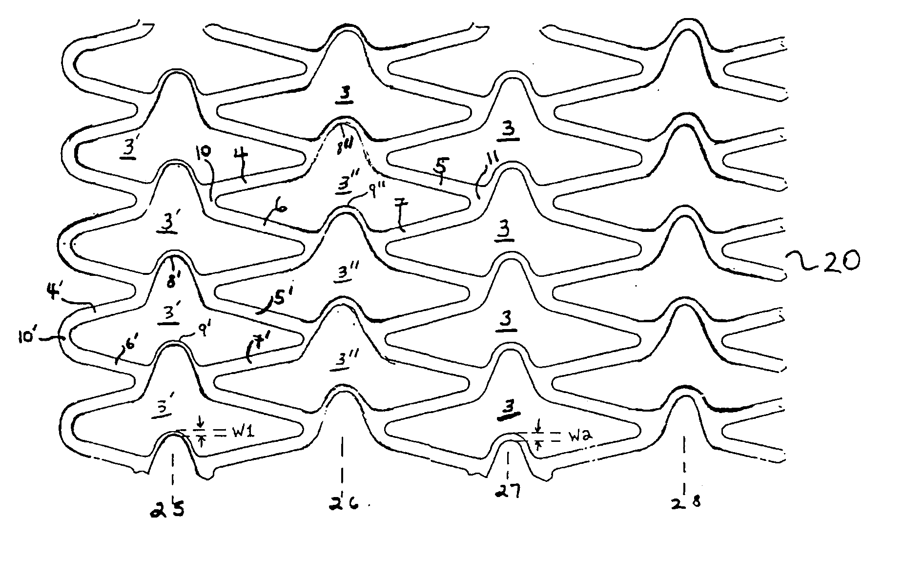
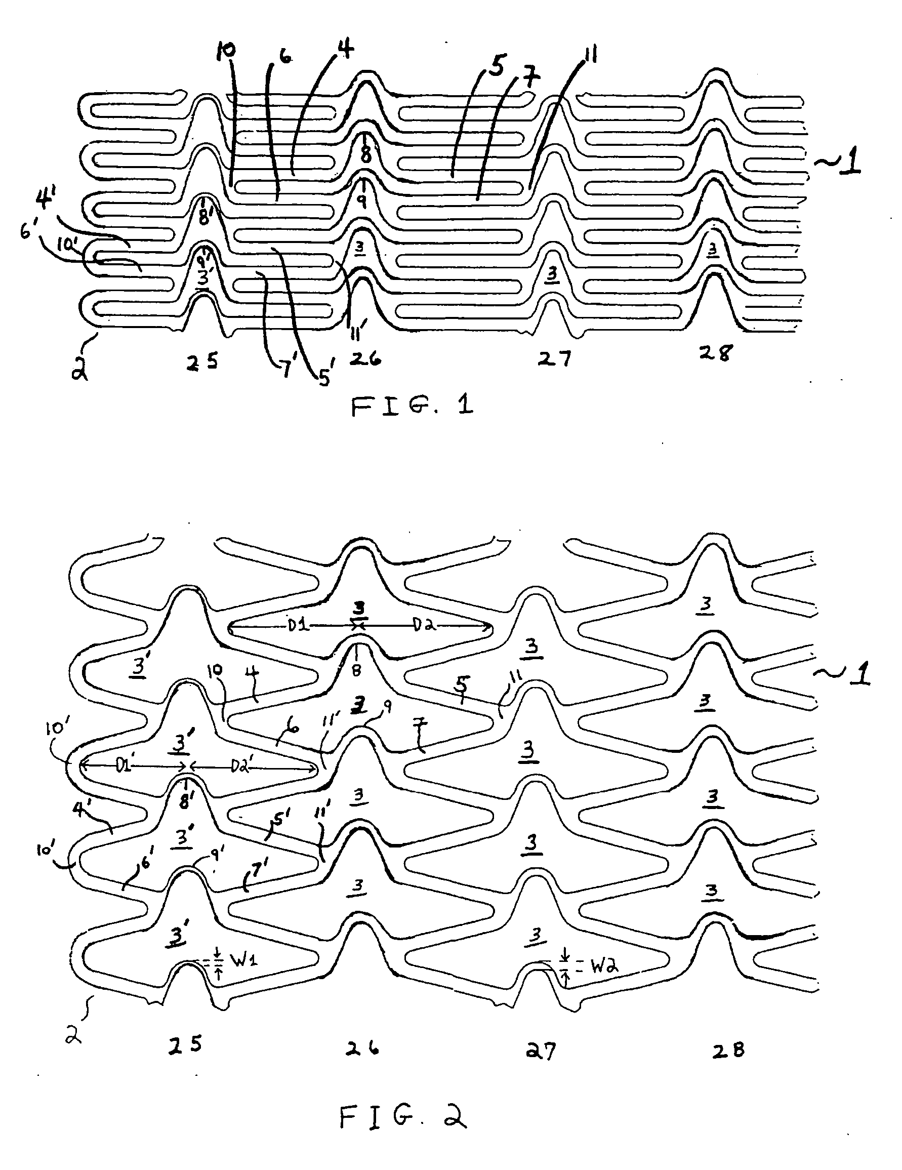
[0036]FIG. 1 shows the general configuration of one embodiment of a stent 1 fabricated in accordance with the present invention. The stent 1 may be fabricated of bio-compatible materials such as stainless steel 316L, gold, tantalum, nitinol or other materials well known to those skilled in the art as suitable for this purpose. The dimensions and gauge of material utilized may be varied as specific applications dictate. The stents of the present invention generally may be constructed in a manner in accordance with the stent described in U.S. patent application Ser. No. 08 / 457,354, filed Jun. 1, 1995, the disclosure of which is incorporated herein by reference.

[0037]FIG. 1 is a side view of the distal end 2 of stent 1 of the present invention, showing the general pattern of the stent. As shown in FIGS. 1 and 2 the pattern may be described as a plurality of cells 3 and 3′. Each cell 3 is provided with a first member 4, a second member 5, a third member 6, and a fourth member 7. A firs...


PUM


Abstract

An intravascular stent especially suited for implanting in lumens having variable characteristics such as curvatures, changing diameters as found in ostial regions or variable wall compliance during systolic cycles. The stent can include an end region which is fabricated to have a greater radial strength than the remaining axial length of the stent. Such a stent is particularly suited for use in ostial regions, which require greater support near the end of the stent. The stent alternatively can include sections adjacent the end of the stent with greater bending flexibility than the remaining axial length of the stent. Such a stent is particularly suited for use in curved arteries. The stent can be constructed with an end that has greater radial strength and sections adjacent the end with greater bending flexibility. Such a stent prevents flaring of the stent end during insertion. The stent can also be constructed to have increased longitudinal flexibility when expanded such that it flexes with the vessel wall during systolic cycles.

Description

CROSS-REFERENCE TO RELATED APPLICATIONS [0001] This application is a continuation-in-part of Ser. No. 09 / 599,158 filed Jun. 21, 2000, which is a continuation of Ser. No. 09 / 040,145 filed Mar. 17, 1998 (now U.S. Pat. No. 6,676,697), which is a division of Ser. No. 08 / 716,039 filed Sep. 16, 1996 (now U.S. Pat. No. 5,807,404).BACKGROUND OF THE INVENTION [0002] 1. Field of the Invention [0003] The present invention relates generally to stents for implanting into vessels of a living body. In particular, the present invention relates to intraluminal stents which provide radial support, stability and coverage of the vessel wall when expanded and which may be especially suited for implanting in a variety of lumens having variable characteristics, such as variable curvature, variable diameter, e.g. as found in ostia, and variable wall compliance during systolic cycles. [0004] 2. Description of the Prior Art [0005] It is well known to use a stent to expand and impart support to different bodi...

Claims


Application Information

Patent Timeline
Patent Type & Authority Applications(United States)
IPC IPC(8): A61F2/90A61F2/84A61F2/00A61F2/02A61F2/06A61F2/82A61M5/00A61M29/00
CPCA61F2/91A61F2/915A61F2002/91533A61F2230/0054A61F2002/91558A61F2250/0018A61F2250/0029A61F2002/91541
Inventor RICHTER, JACOB
Owner MEDINOL LTD
Why Eureka
Try Eureka