Stent delivery balloon catheter having improved stent retention

a balloon catheter and stent technology, applied in the field of catheters, can solve the problems of balloon rupture pressure, stent cannot be so strongly fixed to the balloon, and the system cannot correctly implant the stent into the body lumen, etc., to achieve the effect of reducing the rupture pressure of the balloon, facilitating securely mounting the stent, and maximizing mechanical interferen

Inactive Publication Date: 2006-08-10
ABBOTT CARDIOVASCULAR
View PDF47 Cites 31 Cited by
  • Summary
  • Abstract
  • Description
  • Claims
  • Application Information

AI Technical Summary

Benefits of technology

[0012] Flowing the sleeve material into the stent gaps causes localized thinning of the wall thickness of the sleeve, unlike a stent delivery catheter in which the balloon material maintains a constant wall thickness and deforms around the edges of the stent as the stent is mounted thereon. This localized thinning in the sleeve does not disadvantageously affect performance of the catheter. In contrast, if the balloon material was caused to flow, the localized thinning would result in a reduction of the balloon rupture pressure. Additionally, in an embodiment having a therapeutic agent such as a drug delivery coating on the stent, the low glass transition temperature of the sleeve facilitates securely mounting the stent without exposing the therapeutic agent to high temperatures and/or pressures which can damage the agent or its matrix during stent mounting.
[0013] By flowing the elastomeric material, a permanent imprint is formed. Additionally, the imprint can be made flush with the outer surface of the stent (e.g., so that at least part of the portions of the sleeve protruding between the adjacent stent struts have an outer diameter equal to an outer diameter of the nonexpanded stent), to maximize the mechanical interference between the stent and sleeve. In contrast, if the material underlying the stent is not caused to reflow, as for example if the stent is gently crimped without flowing the underlying material, the imprint is not formed and at most only a temporary and minor mechanical interference is produced between the stent and underlying material. Additionally, because the elastomeric material of the sleeve is caused to flow, it penetrates within very small gaps of densely collapsed stent struts. In contrast, if the material is not caused to reflow, the material does not expand into such small stent gaps, or at least not without damaging the material. Thus, the stent can be collapsed to a greater degree, providing a smaller profile for introduction and advancement within the body lumen.
[0014] The sleeve preferably exerts a radially compressive force on the balloon when it is expanded. As a result, when the inflation pressure inside the balloon is released the sleeve acts to compress the balloon and push the inflation fluid out of the balloon, speeding up the deflation time. Similarly, the sleeve preferably ...

Problems solved by technology

One difficulty has been retention of the stent on the catheter balloon during delivery and deployment of the stent in a patient's body lumen.
If the stent is dislodged from or moved relative to the balloon the system will not c...

Method used


Image

  • Stent delivery balloon catheter having improved stent retention
  • Stent delivery balloon catheter having improved stent retention
  • Stent delivery balloon catheter having improved stent retention

Examples


Embodiment Construction

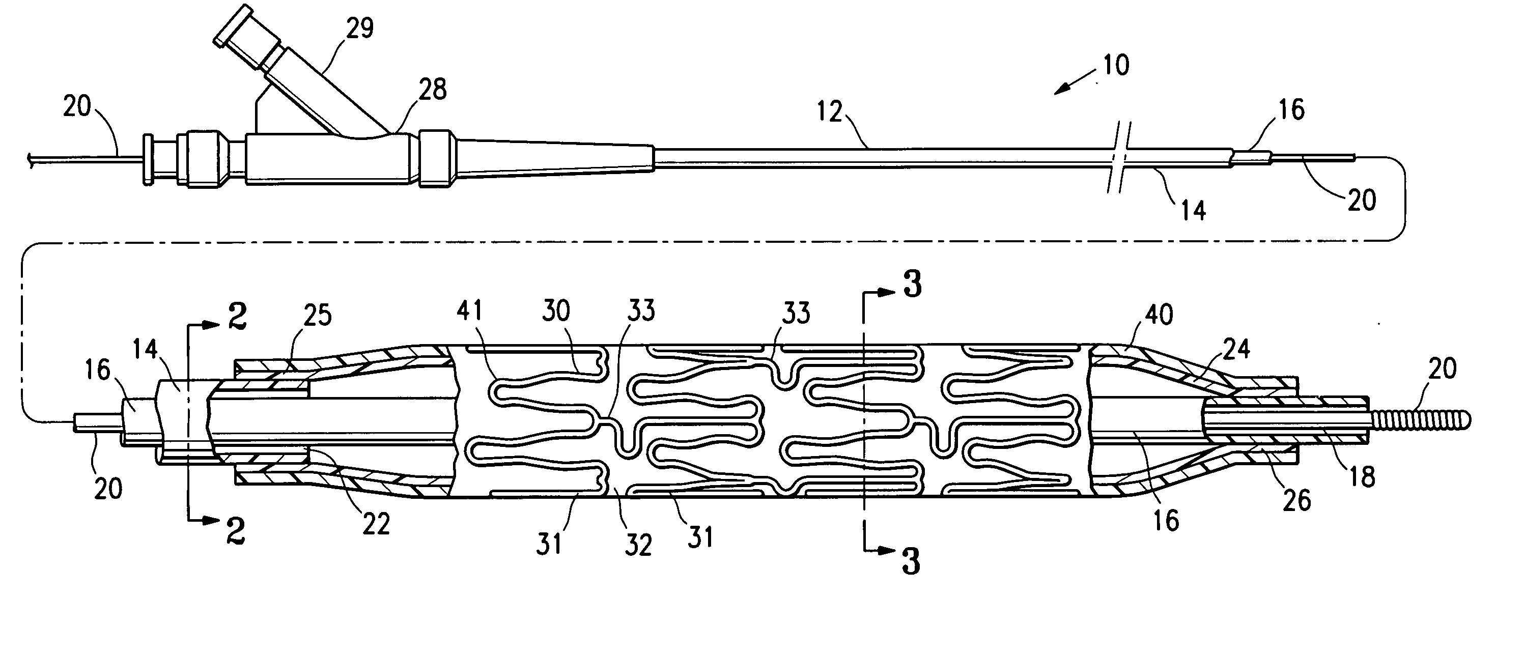
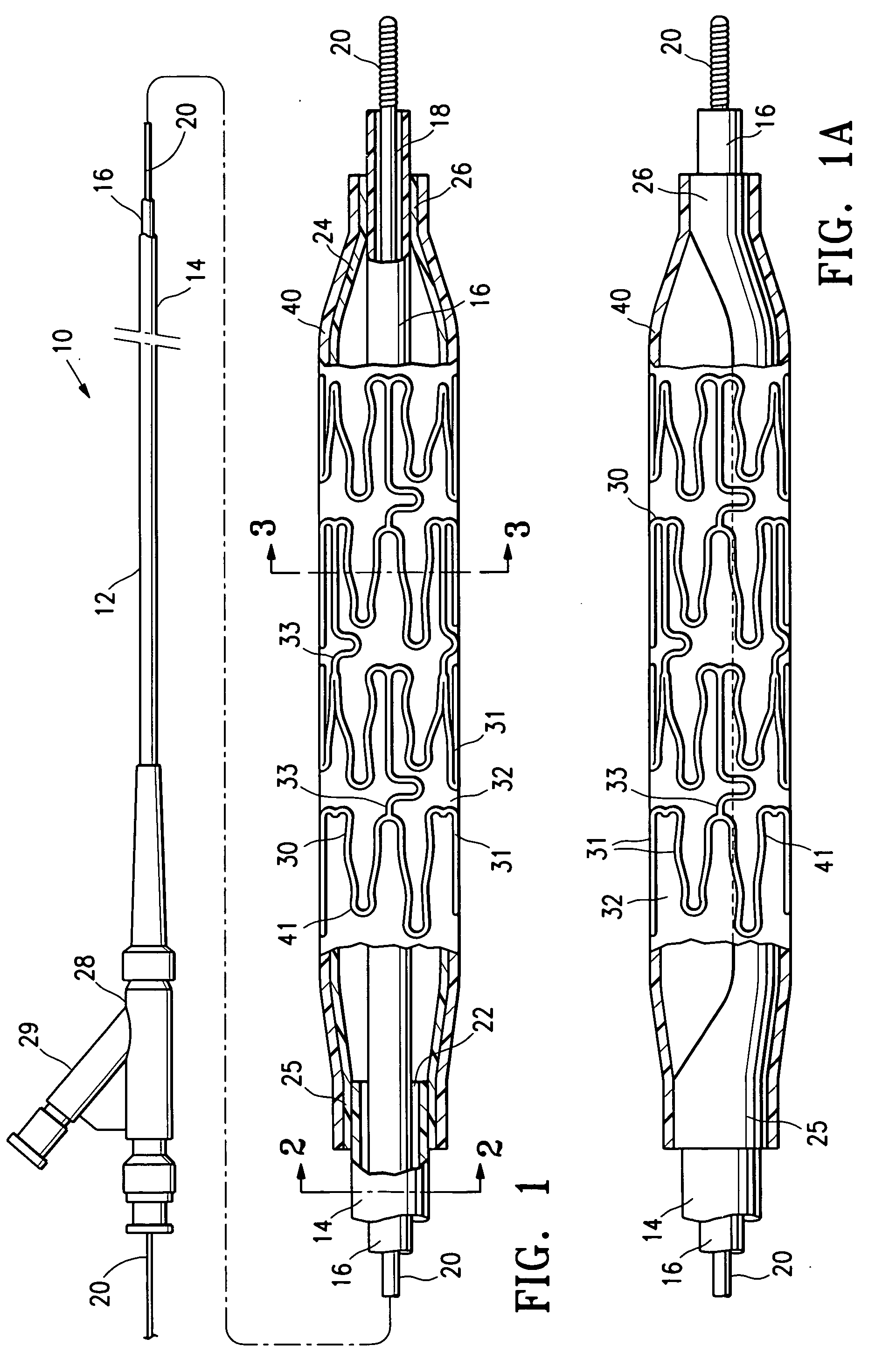
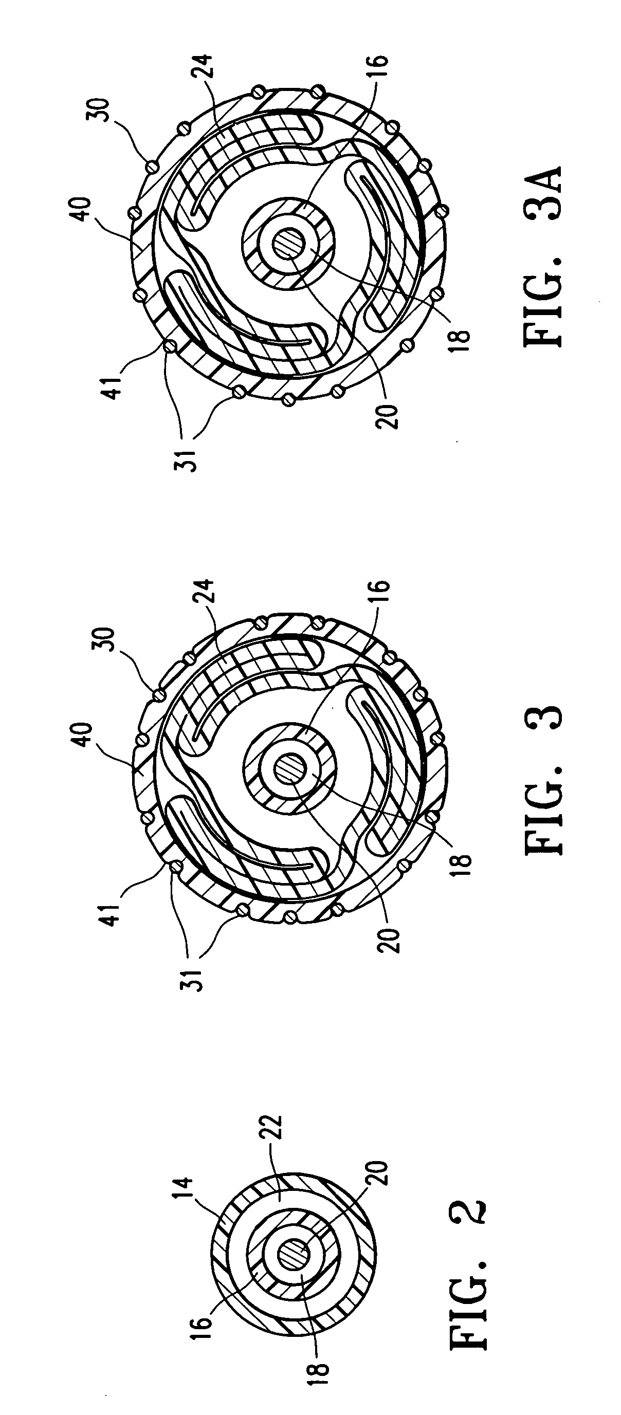
[0026]FIG. 1 illustrates an over-the-wire type stent delivery balloon catheter 10 embodying features of the invention. Catheter 10 generally comprises an elongated catheter shaft 12, an inflatable balloon 24 on a distal shaft section, an elastomeric sleeve 40 on the balloon 24, and a stent 30 mounted on the sleeve 40. In the illustrated embodiment, the shaft comprises an outer tubular member 14 defining an inflation lumen 22 therein, and an inner tubular member 16 defining a guidewire lumen 18 therein configured to slidingly receive a guidewire 20. Specifically, in the illustrated embodiment, the coaxial relationship between outer tubular member 14 and inner tubular member 16 defines annular inflation lumen 22, as best shown in FIG. 2 illustrating a transverse cross section of the distal end of the catheter shown in FIG. 1, taken along line 2-2. In the embodiment illustrated in FIG. 1, the guidewire lumen 18 extends to the proximal end of the catheter. Inflatable balloon 24 has a pr...


PUM


Abstract

A stent delivery balloon catheter having improved stent retention. In one embodiment, a stent mounted on the balloon catheter is embedded in an outer surface of an elastomeric sleeve on the catheter balloon such that the stent forms an imprint in the outer surface of the sleeve. One aspect of the invention is directed to a method of mounting a stent on the balloon catheter. The stent is securely mounted on the balloon due to the interference with the imprinted sleeve.

Description

BACKGROUND OF THE INVENTION [0001] This invention relates generally to catheters, and particularly intravascular catheters for use in the delivery of stents. [0002] In percutaneous transluminal coronary angioplasty (PTCA) procedures a guiding catheter is advanced in the patient's vasculature until the distal tip of the guiding catheter is seated in the ostium of a desired coronary artery. A guidewire is first advanced out of the distal end of the guiding catheter into the patient's coronary artery until the distal end of the guidewire crosses a lesion to be dilated. A dilatation catheter, having an inflatable balloon on the distal portion thereof, is advanced into the patient's coronary anatomy over the previously introduced guidewire until the balloon of the dilatation catheter is properly positioned across the lesion. Once properly positioned, the dilatation balloon is inflated with inflation fluid one or more times to a predetermined size at relatively high pressures so that the ...

Claims


Application Information

Patent Timeline
IPC IPC(8): A61F2/06A61F2/86
CPCA61F2/86A61F2/958A61F2002/9583A61M2025/1004A61M2025/1081A61M2025/1086
Inventor DURCAN, JONATHAN P.WILLIAMS, KERRY J.
Owner ABBOTT CARDIOVASCULAR
Why Eureka
Try Eureka