Method and apparatus for detecting charged state of secondary battery based on neural network calculation

a secondary battery and neural network technology, applied in the field of battery systems, can solve the problems of insufficient detection, fluctuations and changes in measurement precision, difficulty in detecting the soc and/or soh of each secondary battery, and inability to prevent insufficiently, so as to achieve the effect of high precision

Inactive Publication Date: 2006-08-17
DENSO CORP +2
View PDF10 Cites 154 Cited by
  • Summary
  • Abstract
  • Description
  • Claims
  • Application Information

AI Technical Summary

Benefits of technology

[0013] The present invention has been completed with the above view in mind and has an object to provide a method and apparatus for detecting charged state of a secondary battery based on neural network calculation, which is able to provide an output parameter with a higher precision, regardless of differences in charge and discharge characteristics of individual batteries, the differences resulting from, for example, degrees of temporal degradations (cycle degradations) and / or differences in battery types.

Problems solved by technology

These problems make it difficult to detect, with precision, the SOC and / or SOH of each of secondary batteries which are mass-produced.
However, even when the SOC and / or SOH are detected using the conventional neural network type of detection apparatus, fluctuations and changes in the measurement precision, which are due to degradations in the battery, cannot be prevented sufficiently.
The existence of those various different correlations makes it difficult to absorb the fluctuations and changes in the measurement precision even when calculation is made using the neural network.
However, even when the present values of such physical quantities are taken into account as part of the input parameters, a substantial progress in the degradation of the battery makes it difficult to attain or keep a practically-required higher level in detecting the SOC and / or SOH.
However, such a configuration is not favorable, because the calculator becomes large in its circuit size, a calculation load increases, and power is consumed much.

Method used


Image

  • Method and apparatus for detecting charged state of secondary battery based on neural network calculation
  • Method and apparatus for detecting charged state of secondary battery based on neural network calculation
  • Method and apparatus for detecting charged state of secondary battery based on neural network calculation

Examples


first embodiment

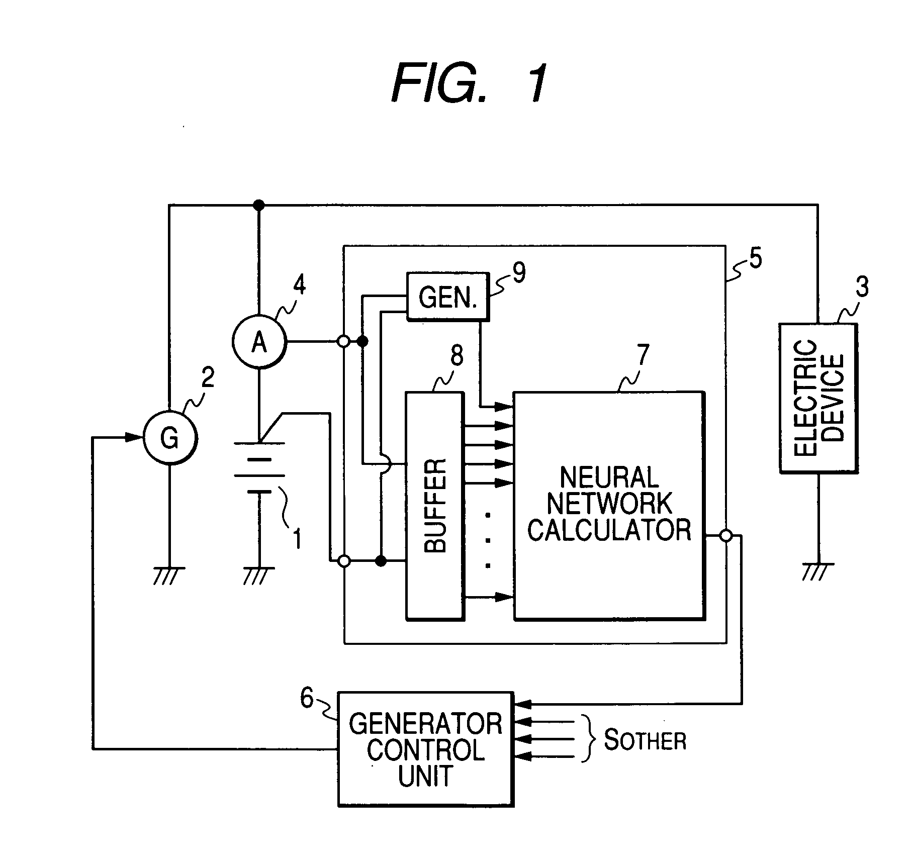
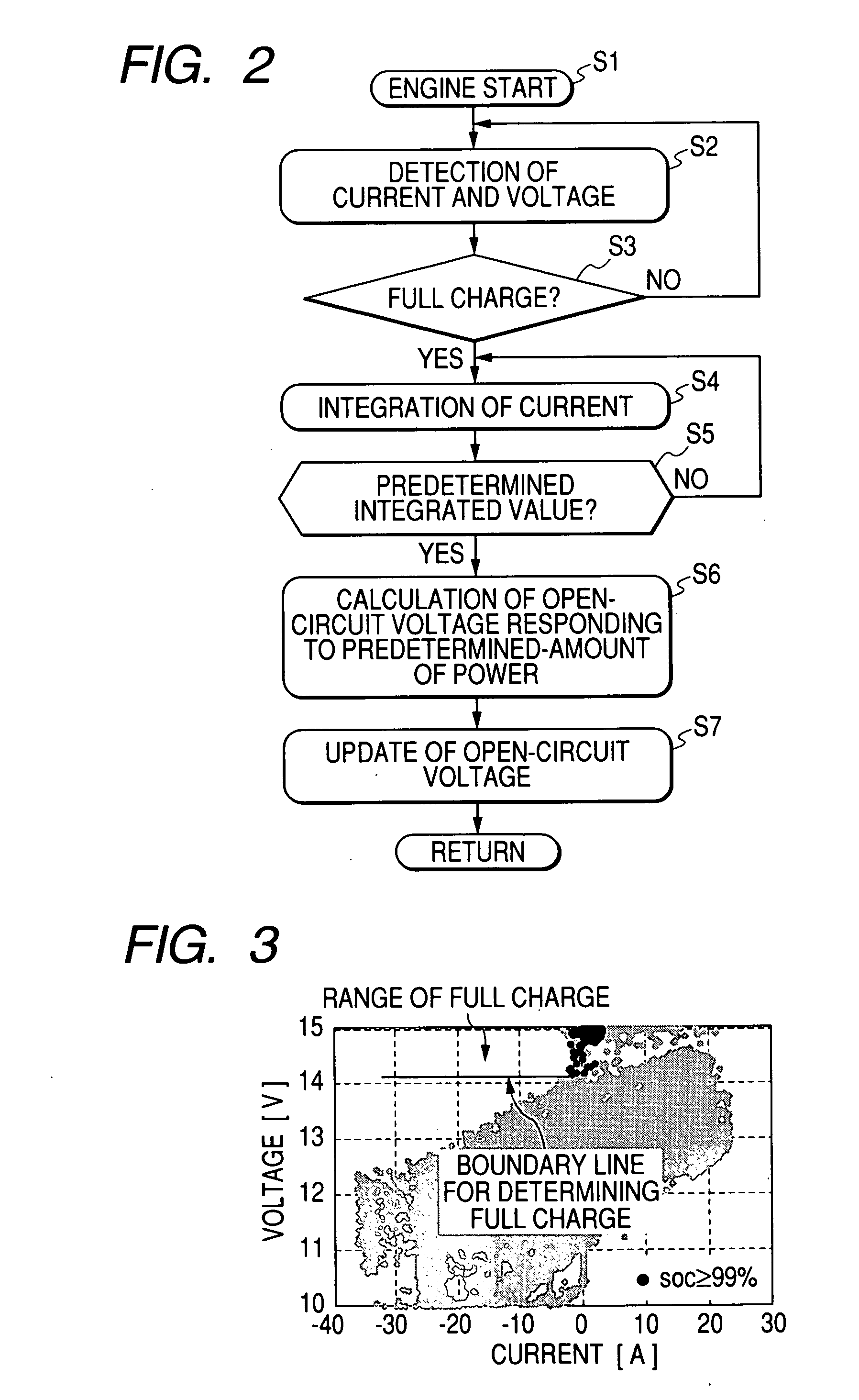
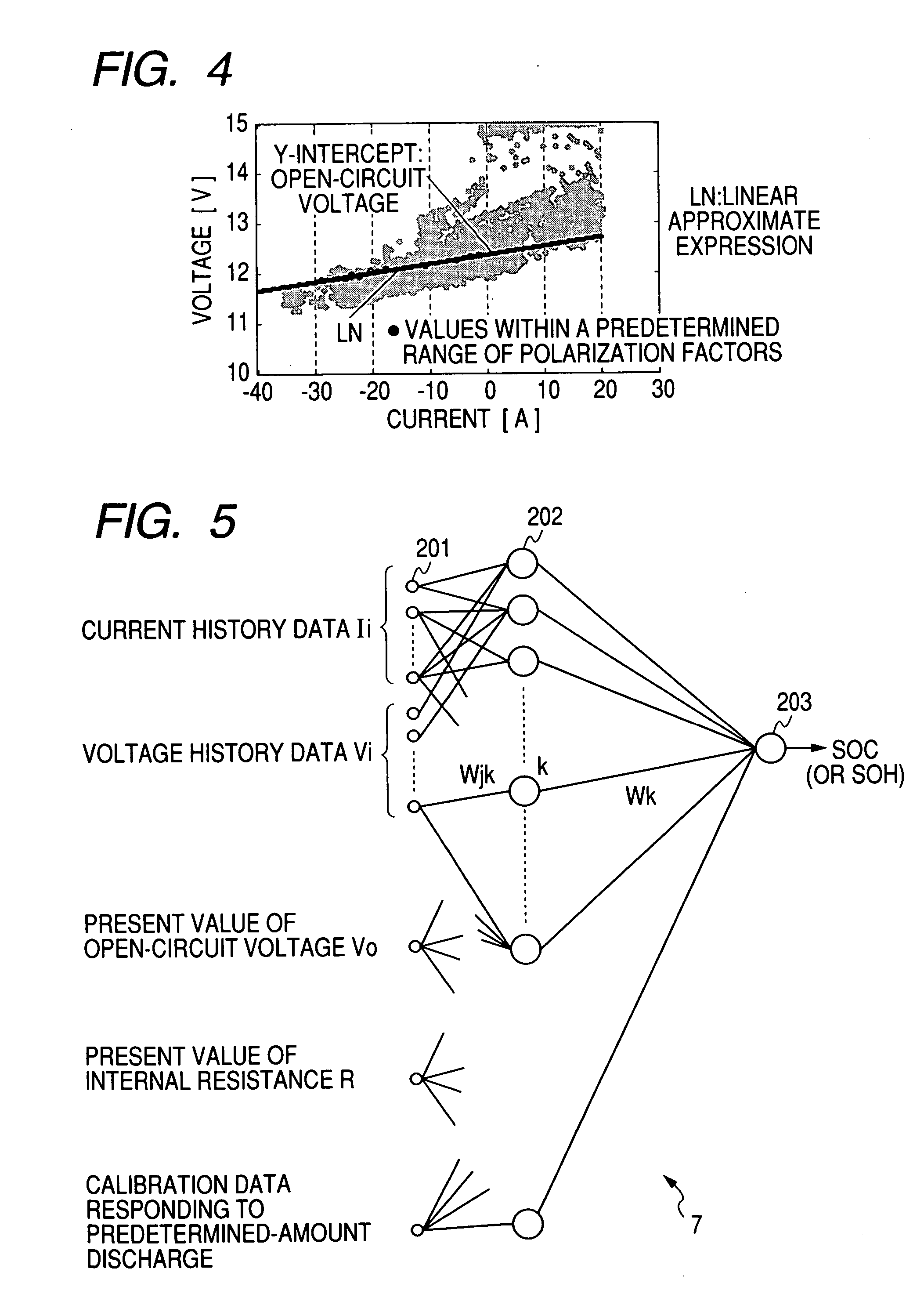
[0109] Referring to FIGS. 1-9, a first embodiment of the on-vehicle battery system will now be described. This on-vehicle battery system is based on neural network type of calculation and corresponds to a battery system according to the present invention.

[0110] As shown in FIG. 1, the on-vehicle battery system is provided with an on-vehicle battery (hereinafter, simply referred to as a “battery”) 1 and other electric components including an on-vehicle generator 2, an electric device(s) 3, a current sensor 4, a battery state detector 5, and a generator control unit 6. Of these, as shown, the battery state detector 5 is equipped with a neural network calculator 7, a buffer 8, and a correcting signal generator 9 and may be, in part or as a whole, formed by either a computer configuration or a structure on digital / analog circuitry.

[0111] The on-vehicle generator 2 is mounted on the vehicle to charge the battery 1 and power the electric device 3. The electric device 3 functions as an o...

second embodiment

[0157] Referring to FIGS. 10 to 14, a second embodiment according to the on-vehicle battery system of the present invention will now be described.

[0158] The on-vehicle battery system adopted in the second embodiment is the same or equivalent as or to that adopted in the first embodiment except for the operations of the correcting signal generator. Thus, for the sake of simplified explanations, those components which are the same or equivalent as or to those in the first embodiment are given the same reference numerals and omitted from being described in detail. This manner will also be true of the succeeding embodiments.

[0159] As shown in FIG. 10, the second embodiment adopts a battery state detector 15 with a correcting signal generator 19 which is configured to use a difference ΔV between two open-circuit voltages Vo, which is different from the first embodiment. In the first embodiment, used is only the open-circuit voltage Vo detected when the battery 1 discharges in its full ...

third embodiment

[0168] Referring to FIGS. 15 to 24, a third embodiment according to the on-vehicle battery system of the present invention will now be described.

[0169] The configurations and operations of the system in the third embodiment is essentially the same as those in the foregoing embodiments, but the correcting signal generator and neural network calculator are different in their configurations and operations from the foregoing.

[0170] The on-vehicle battery system according to the present embodiment is provided with a battery state detector 25 with a correcting signal generator 29 and a neural network calculator 17, instead of those shown in the foregoing.

[0171] The correcting signal generator 29 adopts, as calibration data, the internal resistance R of the battery 1 detected when a predetermined amount of power is discharged in the full charge state, in place of the open-circuit voltage detected in discharging a predetermined amount of power in the full charge state. On the other hand,...


PUM


Abstract

A neural network type of apparatus is provided to detect an internal state of a secondary battery implemented in a battery system. The apparatus comprises a detecting unit, producing unit and estimating unit. The detecting unit detects electric signals indicating an operating state of the battery. The producing unit produces, using the electric signals, an input parameter required for estimating the internal state of the battery. The input parameter reflects calibration of a present charged state of the battery which is attributable to at least one of a present degraded state of the battery and a difference in types of the battery. The estimating unit estimates an output parameter indicating the charged state of the battery by applying the input parameter to neural network calculation.

Description

CROSS REFERENCES TO RELATED APPLICATIONS [0001] The present application relates to and incorporates by reference Japanese Patent application Nos. 2005-036442 filed on Feb. 14, 2005, 2005-036437 filed on Feb. 14, 2005, 2005-039614 filed on Feb. 16, 2005, 2005-122011 filed on Apr. 20, 2005, 2005-122004 filed on Apr. 20, 2005, and 2005-151050 filed on May 24, 2005. BACKGROUND OF THE INVENTION [0002] 1. Field of the Invention [0003] The present invention relates to a battery system with a neural network type of apparatus for detecting a charged state of a secondary (rechargeable) battery, and in particular, to an improvement in detection of the charged state of such a battery which is for example mounted on vehicles. [0004] 2. Description of the Related Art [0005] An on-vehicle battery system is mostly composed of a secondary battery such as lead batteries. In the secondary battery, degrees of degradation give fluctuations to correlations between electric quantities of a battery, such a...

Claims


Application Information

Patent Timeline
Patent Type & Authority Applications(United States)
IPC IPC(8): H02J7/00
CPCG01R31/3624G01R31/3648G01R31/3651G01R31/3842G01R31/367F25D16/00F25D23/068F25D2201/12
Inventor MIZUNO, SATORUHASHIKAWA, ATSUSHISAKAI, SHOJIICHIKAWA, ATSUSHIKOZAWA, TAKAHARUMIZUNO, NAOKIMORITA, YOSHIFUMI
Owner DENSO CORP
Why Eureka
Try Eureka