Oxidizing method and oxidizing unit of object for object to be processed

a technology of oxidizing unit and object, which is applied in the direction of conveyor parts, transportation and packaging, coatings, etc., can solve the problems the design rules of semiconductor integrated circuits have become more severe, and the uniformity between surfaces of the film thickness of oxide films is difficult to achieve. achieve the effect of reducing the width and/or film thickness, and maintaining high uniformity

Active Publication Date: 2006-08-17
TOKYO ELECTRON LTD
View PDF3 Cites 6 Cited by
  • Summary
  • Abstract
  • Description
  • Claims
  • Application Information

AI Technical Summary

Benefits of technology

[0022] This invention is developed by focusing the aforementioned problems in order to resolve them effectively. The object of this invention is to provide an oxidizing method and an oxidizing unit for an object to be processed, wherein uniformity between surfaces of a fi

Problems solved by technology

In addition, in general, an oxide film formed by a wet oxidizing process under a normal pressure can achieve a great oxidation rate, but is inferior in uniformity within a surface of a film thickness.
However, recently, a wire width and/or a film thickness have been decreased so that the design rules for a semiconductor integrated circuit have become more severe.
The conventional oxidizing methods can not cope with the requests sufficiently.
That is, uniformity between surfaces of a film thickness o

Method used


Image

  • Oxidizing method and oxidizing unit of object for object to be processed
  • Oxidizing method and oxidizing unit of object for object to be processed
  • Oxidizing method and oxidizing unit of object for object to be processed

Examples


Embodiment Construction

[0049] Hereinafter, an embodiment of an oxidizing method and an oxidizing unit according to the present invention is explained with reference to attached drawings.

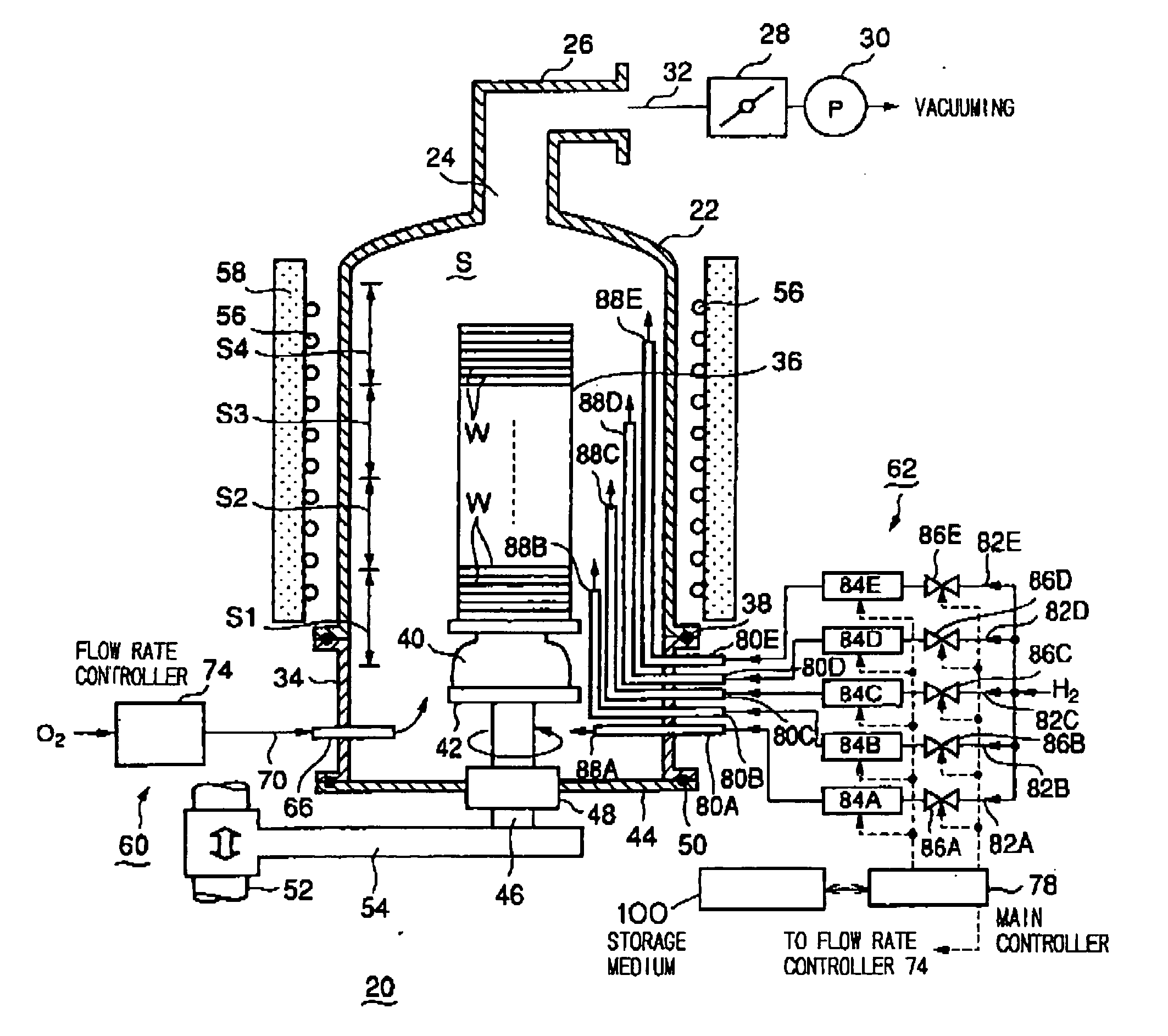
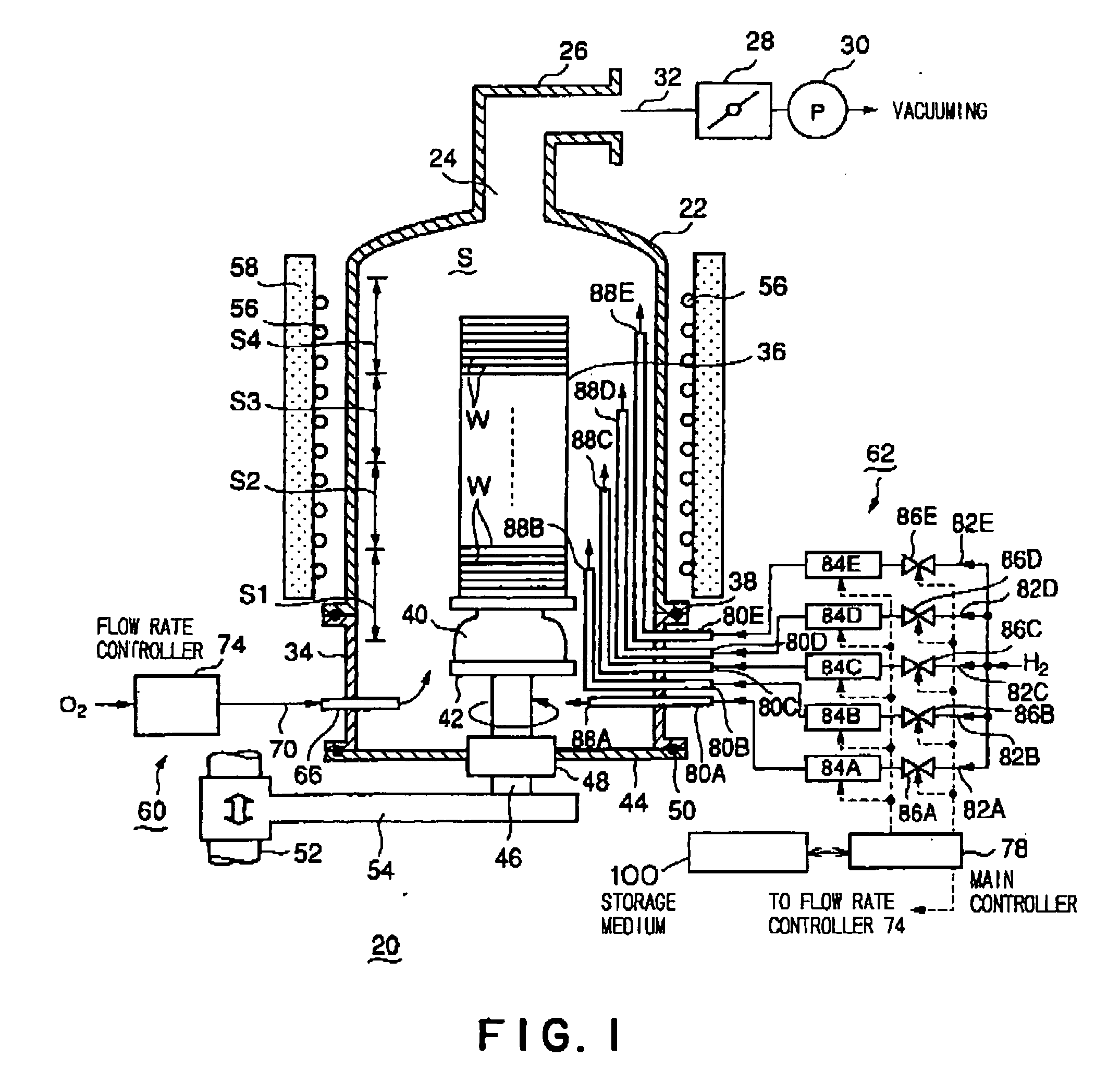
[0050]FIG. 1 is a schematic structural view showing the embodiment of an oxidizing unit according to the present invention.

[0051] As shown in FIG. 1, an oxidizing unit 20 according to the embodiment of the invention has a cylindrical processing container 22 whose lower end is open. The processing container 22 may be made of for example quartz whose heat resistance is high. The processing container 22 has a predetermined length.

[0052] An open gas-discharging port 24 is provided at a ceiling part of the processing container 22. A gas-discharging line 26 that has been bent at a right angle in a lateral direction is provided to connect with the gas-discharging port 24. A gas-discharging system 32 including a pressure-control valve 28 and a vacuum pump 30 and the like on the way is connected to the gas-discharging line 26. T...


PUM

PropertyMeasurementUnit
Fractionaaaaaaaaaa
Fractionaaaaaaaaaa
Lengthaaaaaaaaaa

Abstract

An oxidizing method for an object to be processed according to the present invention includes: an arranging step of arranging a plurality of objects to be processed in a processing container whose inside can be vacuumed, the processing container having a predetermined length, a supplying unit of an oxidative gas being provided at one end of the processing container, a plurality of supplying units of a reducing gas being provided at a plurality of positions in a longitudinal direction of the processing container; an atmosphere forming step of supplying the oxidative gas and the reducing gas into the processing container in order to form an atmosphere having active oxygen species and active hydroxyl species in the processing container; and an oxidizing step of oxidizing surfaces of the plurality of objects to be processed in the atmosphere. The atmosphere forming step has: a selecting step of selecting a predetermined supplying unit of a reducing gas among the plurality of supplying units of a reducing gas, based on an arrangement number and respective arrangement positions of the plurality of objects to be processed in the processing container; an oxidative-gas supplying step of supplying the oxidative gas into the processing container by means of the supplying unit of an oxidative gas; and an reducing-gas supplying step of supplying the reducing gas into the processing container by means of only the supplying unit of a reducing gas selected by the selecting step.

Description

FIELD OF THE INVENTION [0001] This invention relates to an oxidizing method and an oxidizing unit for an object to be processed such as a semiconductor wafer or the like, which carries out an oxidation process to a surface of the object to be processed. BACKGROUND ART [0002] In general, in order to manufacture a desired semiconductor integrated circuit, various thermal processes including a film-forming process, an etching process, an oxidation process, a diffusion process, a modifying process or the like are carried out to a semiconductor wafer, which consists of a silicon substrate or the like. For example, as an oxidation process, there are known an oxidation process that oxidizes a surface of a single-crystal silicon film or a poly-silicon film, and another oxidation process that oxidizes a metal film, and so on. Such an oxidation process is mainly used for forming an insulation film such as a gate oxide film or a capacitor. [0003] In view of a pressure, there are a normal-press...

Claims


Application Information

Patent Timeline
IPC IPC(8): H01L21/31H01L21/00H01L21/316H01L21/677
CPCH01L21/02238H01L21/02255H01L21/67757H01L21/67017H01L21/31662H01L21/02271H01L21/02554H01L21/67098
Inventor SUZUKI, KEISUKEIKEUCHI, TOSHIYUKIUMEZAWA, KOTA
Owner TOKYO ELECTRON LTD
Why Eureka
Try Eureka