
Multi-channel infrared optical phase fraction meter

a multi-channel, infrared technology, applied in the direction of optical radiation measurement, liquid/fluent solid measurement, instruments, etc., can solve the problems of occupying a considerably larger space for three phase separators, requiring manual sampling, and two phase separators, so as to improve the accuracy and/or the range of operating conditions, improve performance, and save costs

Active Publication Date: 2006-08-24
WEATHERFORD TECH HLDG LLC
View PDF5 Cites 24 Cited by
  • Summary
  • Abstract
  • Description
  • Claims
  • Application Information

AI Technical Summary

Benefits of technology

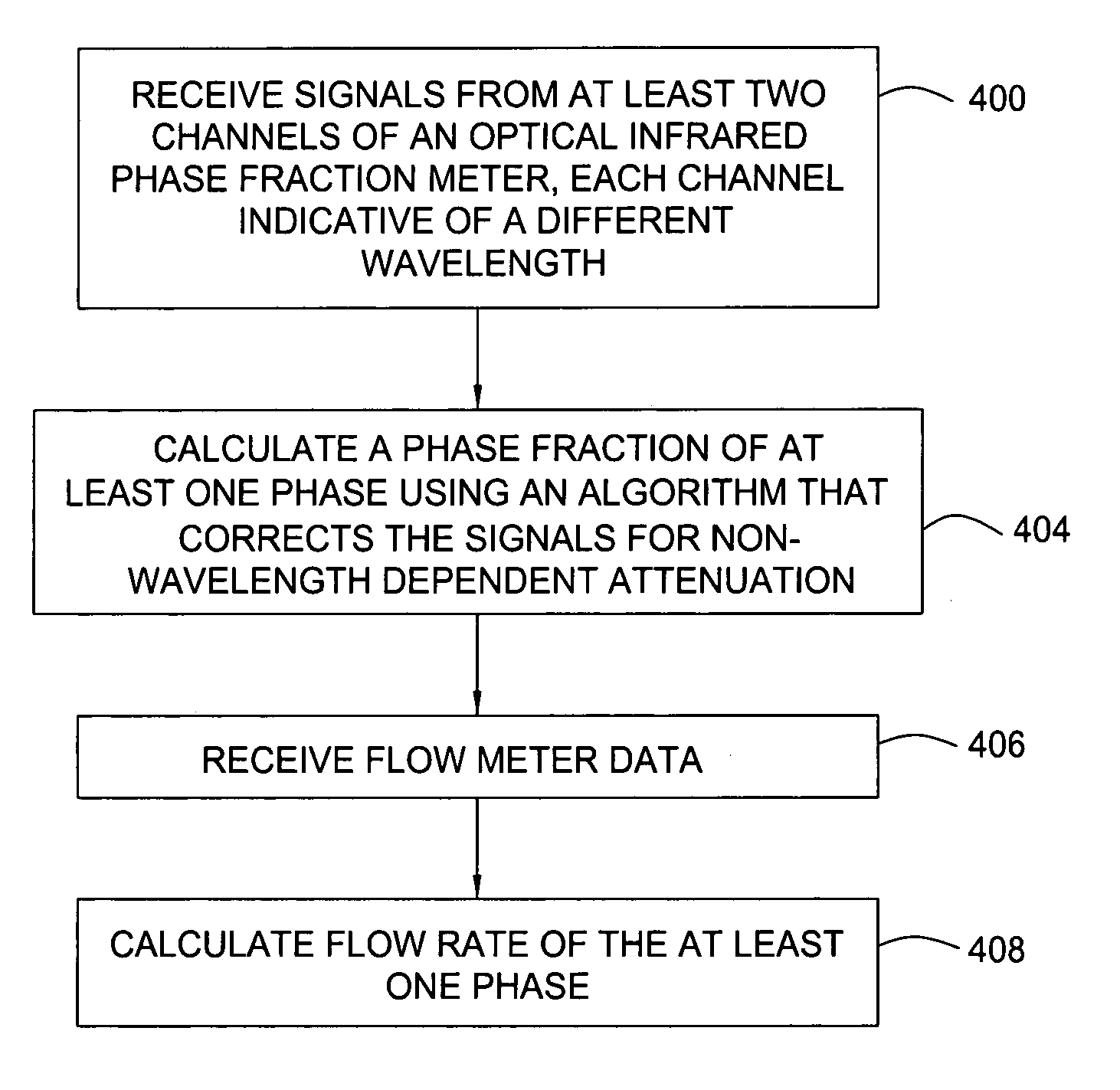
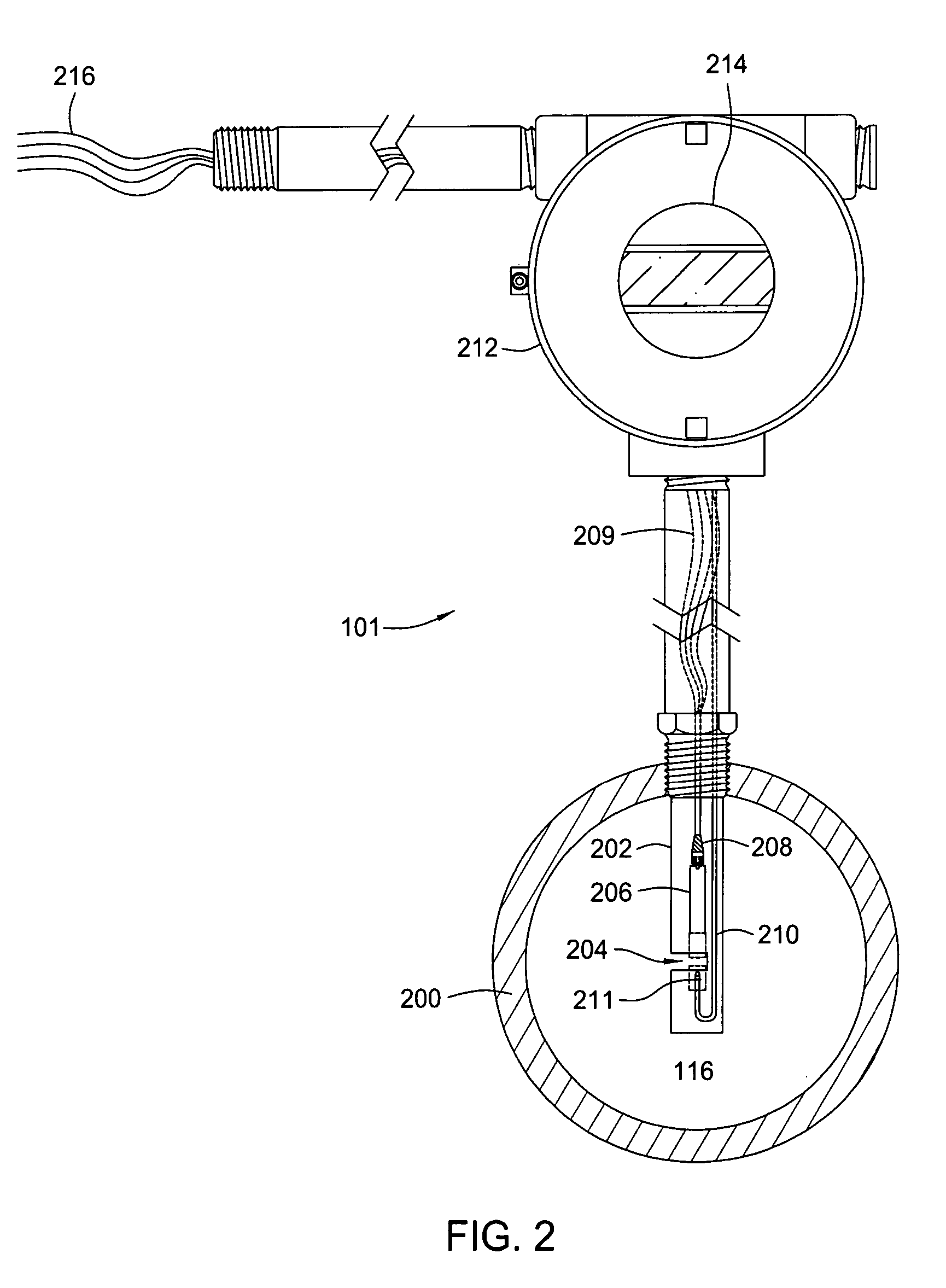
[0010] Embodiments of the invention generally relate to methods and apparatus for measuring a phase fraction of a flow stream. According to some embodiments, an infrared phase fraction meter includes a light source for emitting into a flow stream infrared radiation that includes first second, third, and fourth wavelength bands. One wavelength is predominantly an oil absorber, one is predominantly a water absorber, one is predominantly a reference and the fourth is an extra. The extra may be used as a second oil absorber to improve performance over a wide range of oil types. While only a difference in absorption at one wavelength for two of the three phase fractions (nominally water and oil) is required, the additional wavelength bands improve accuracy and / or range of operating conditions. In some applications, two or three wavelength bands suffice, and the other channels are not populated to save costs. The first wavelength band substantially transmits through first and second phases of the flow stream and is substantially absorbed by a third phase. In contrast, the second wavelength band is substantially absorbed by the second phase relative to the first and third phases. One or more detectors simultaneously detect attenuation of the first and second wavelength bands upon the infrared radiation passing through at least a portion of the flow stream, and a phase fraction of the second phase is determined based on the attenuation. As an example, the first, second and third phases are gas, water and oil, respectively, produced from a well.

Problems solved by technology

This typically requires the time-consuming and expensive process of manual sampling or the use of an online device called a water cut meter.
However, the three phase separator occupies a considerably larger space than the simpler two phase separators and is more expensive to own and operate.
Further, inefficient separation or the propensity of certain oils to bind water in a tight emulsion still necessitates manual sampling in the oil and water legs.
However, capacitive, density and microwave water cut meters each possess particular limitations.
In general, these limitations include detection of oil-water concentrations only within a limited range, calibration difficulties, high costs, and results affected by the presence of gas bubbles, salinity fluctuations and density changes or close densities of oil and water.
However, problems such as non-absorbance based signal attenuation and low water cuts can prevent accurate measurements using the infrared optical sensors.

Method used


Image

  • Multi-channel infrared optical phase fraction meter
  • Multi-channel infrared optical phase fraction meter
  • Multi-channel infrared optical phase fraction meter

Examples


Embodiment Construction

[0018] Embodiments of the invention generally relate to phase fraction meters that utilize infrared optical analysis techniques. While the phase fraction meter is illustrated as part of a test system that detects phase fractions from a flow stream being produced from a well, use of the phase fraction meter includes various other applications. For example, the phase fraction meter can be used to monitor flows associated with an overboard discharge treatment facility that treats the water produced from the well prior to its discharge into an ocean. Additionally, other industries such as pharmaceutical, food, refinery, chemical, paper, pulp, petroleum, gas, mining, minerals and other fluid processing plants often utilize phase fraction meters in order to detect such aspects as water content.

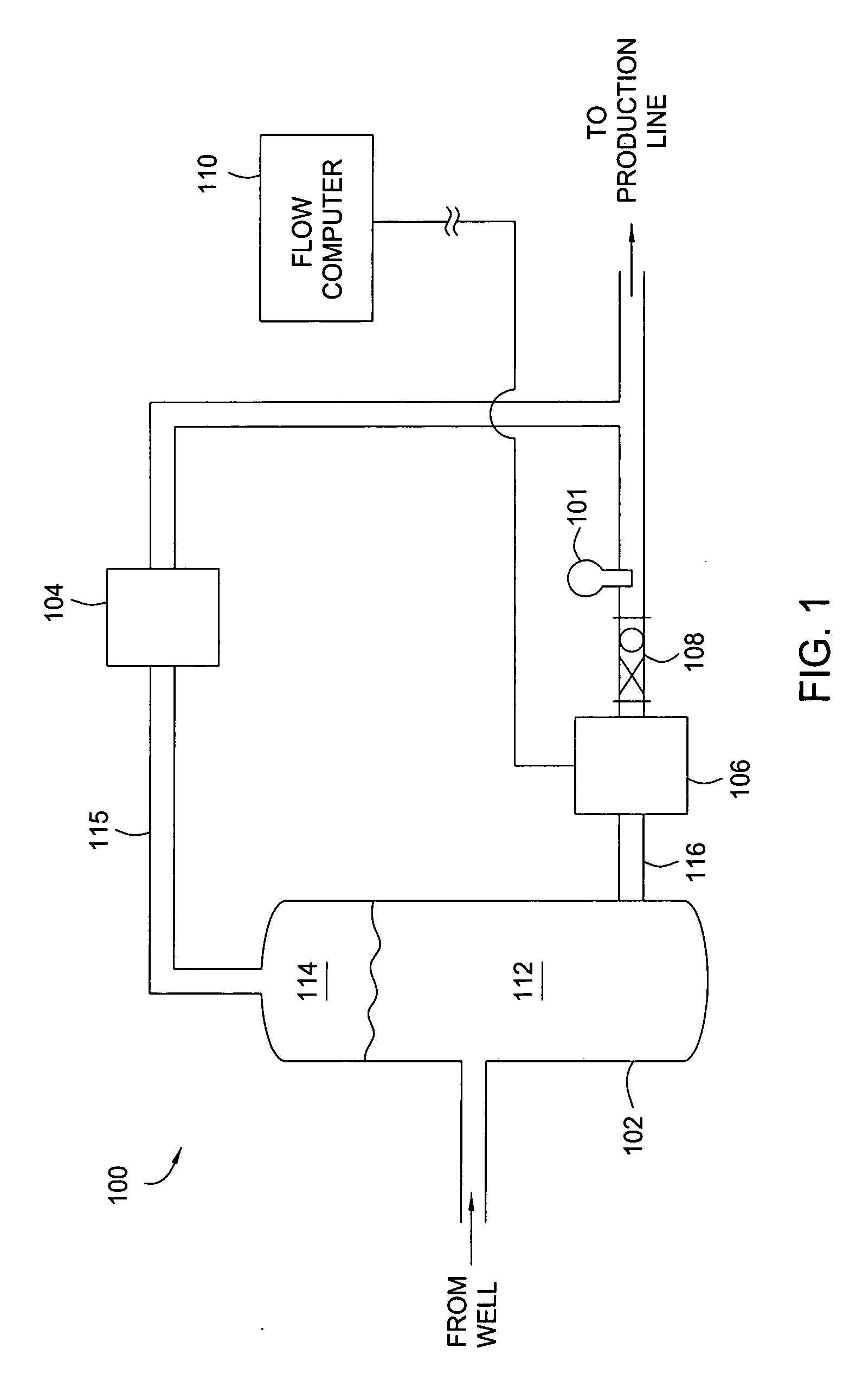
[0019]FIG. 1 shows a well testing system 100 including an infrared phase fraction meter 101 in accordance with embodiments of the invention. U.S. Pat. Nos. 6,076,049 and 6,292,756, which are herein...


PUM


Abstract

Methods and apparatus for measuring a phase fraction of a flow stream are disclosed. An infrared phase fraction meter includes a light source for emitting into a flow stream infrared radiation that includes first and second wavelength bands. The first wavelength band substantially transmits through first and second phases of the flow stream and is substantially absorbed by a third phase. In contrast, the second wavelength band is substantially absorbed by the second phase relative to the first and third phases. One or more detectors simultaneously detect attenuation of the first and second wavelength bands upon the infrared radiation passing through at least a portion of the flow stream, and a phase fraction of the second phase is determined based on the attenuation. As an example, the first, second and third phases are gas, water and oil, respectively, produced from a well.

Description

BACKGROUND OF THE INVENTION [0001] 1. Field of the Invention [0002] Embodiments of the invention generally relate to phase fraction meters such as water cut meters, and more particularly to an infrared optical phase fraction meter. [0003] 2. Description of the Related Art [0004] Oil and gas wells often produce water along with hydrocarbons during normal production from a hydrocarbon reservoir within the earth. The water resident in the reservoir frequently accompanies the oil and / or gas as it flows up to surface production equipment. Operators periodically measure the fractions of an overall production flow stream that are water / oil / gas for purposes such as improving well production, allocating royalties, properly inhibiting corrosion based on the amount of water and generally determining the well's performance. [0005] In many cases, several wells connect to a manifold in order to selectively isolate one of the wells and measure phase fractions of the production flow from that well....

Claims


Application Information

Patent Timeline
IPC IPC(8): G01N21/35
CPCG01F1/74G01N21/314G01N21/3554G01F1/661G01N21/3559G01N21/35G01N33/2823
Inventor LIEVOIS, JOHNATKINSON, DAVID
Owner WEATHERFORD TECH HLDG LLC
Learn More