Low-loss filter and frequency multiplexer

a low-loss filter and frequency multiplexer technology, applied in the field of compact low-loss ridgewaveguide filters, can solve the problems of unit size and production cost, thermal constraints may add to design challenges, and sacrifice filter performance, and achieve the effect of raising the cutoff frequency

Inactive Publication Date: 2006-08-24
THE UNITED STATES OF AMERICA AS REPRESENTED BY THE SECRETARY OF THE NAVY
View PDF11 Cites 11 Cited by
  • Summary
  • Abstract
  • Description
  • Claims
  • Application Information

AI Technical Summary

Benefits of technology

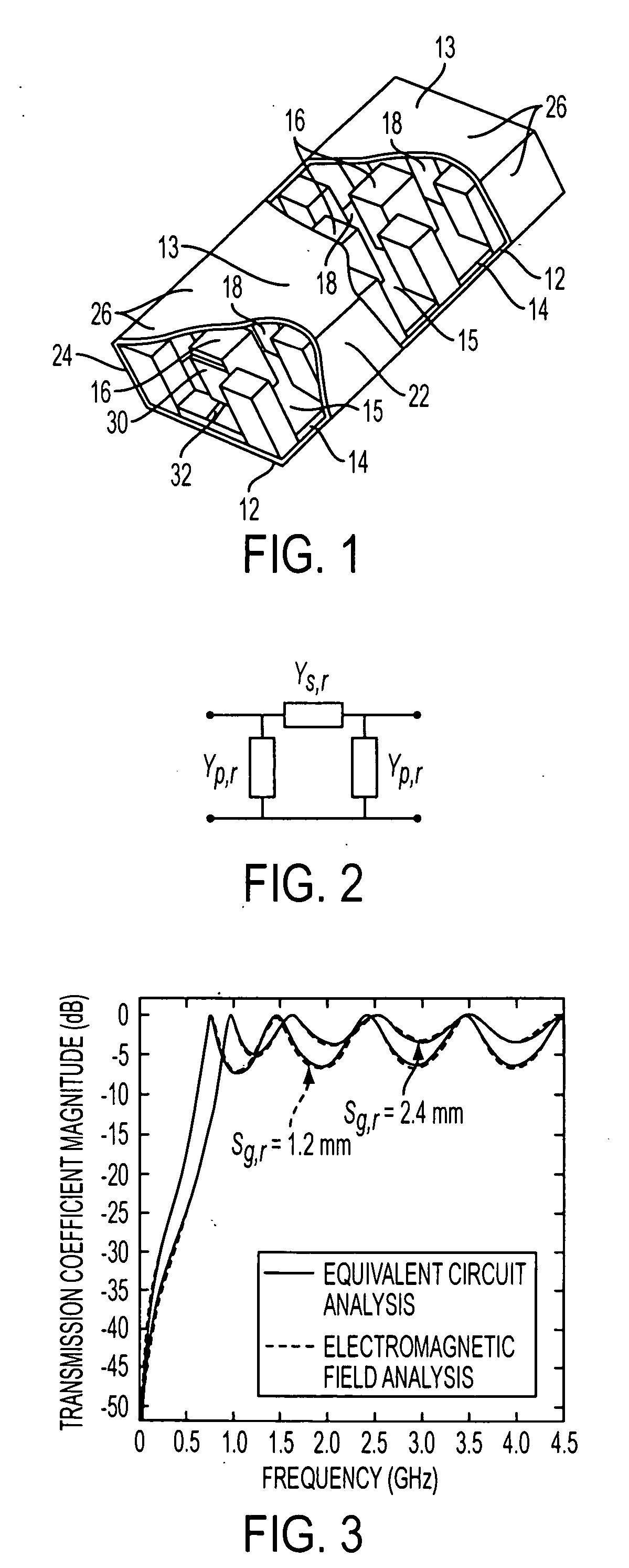
[0015] 3) the realization of evanescent-mode-waveguide inter-resonator coupling segments with widths of these segments narrower than the width of the main, preferably ridge-type waveguide, so as to raise the cutoff frequencies in the evanescent-mode regions;

Problems solved by technology

The perennial challenge is to reduce unit size and production cost without undue sacrifice of filter performance.
In the latter, thermal constraints may add to the design challenge.
Among the principal drawbacks of these formats is elevated passband insertion loss that results from high current densities at the conductive strips' thin edges.
Under resonant conditions, as encountered especially in bandpass filters, this invariably leads to high signal attenuation at passband frequencies and compromised frequency selectivity.
A further concern may arise when dielectric layers of relatively poor thermal conductivity impede the extraction of loss-induced heat from the strip conductors, with power handling limited by heat-generated mechanical stresses.
Among the drawbacks of conventional 3D-waveguide filters are bandwidth limitations imposed by the practical need to operate in a regime where electromagnetic waves propagate only in a single mode.
The limitations result from the absence of wave propagation below a geometry-determined cutoff frequency and the emergence of higher-order wave-propagation modes above a geometry-determined upper frequency limit.
As an example, for common rectangular waveguide, the upper frequency bound is generally twice the low-end cutoff frequency, which imposes unacceptable constraints in cases where filters must cover multiple octaves.
Furthermore, per-unit fabrication costs of 3D waveguide filters are generally higher than for contending planar-circuit counterparts.

Method used


Image

  • Low-loss filter and frequency multiplexer
  • Low-loss filter and frequency multiplexer
  • Low-loss filter and frequency multiplexer

Examples


experiment b

[0087] Experiment B

[0088] The technique is further demonstrated with a second experimental five-pole bandpass filter that exhibits a 6-8.6-GHz passband width and is configured according to the same generic block diagram of FIG. 8 as in Experiment A. The cross-sectional views of filter 100 are represented in FIG. 12, where the structural components are the same as illustrated in FIG. 1 and FIG. 10 save for microstrip port matching circuits 34 replacing former series capacitors 30 and microstrip feeder lines 32, and a solid dielectric core of one material replacing former dielectric layers 14 and 15 of differing materials. Referring to FIG. 12, as above, ag,r, ag,e, and bg,r represent ridge-waveguide width, evanescent-mode-waveguide width, and common waveguide height, respectively, lg,r1, lg,r2, lg,r3, and lg,e12, lg,e23 denote respective ridge-waveguide and evanescent-mode-waveguide lengths, wg,r refers to ridge width, and sg,r to ridge gap spacing. The ratio of waveguide height bg,r...


PUM

PropertyMeasurementUnit
dielectric constantaaaaaaaaaa
relative dielectric constantsaaaaaaaaaa

Abstract

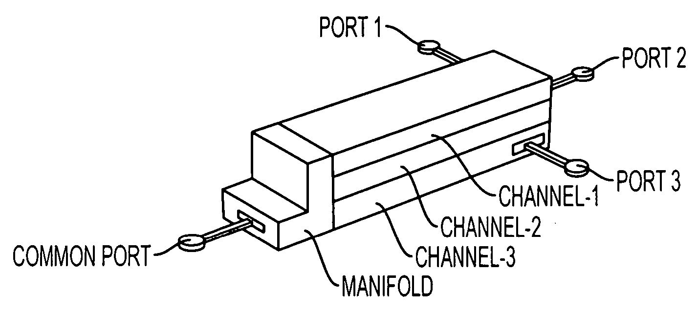
A waveguide filter with a signal input port at a first end and a signal output port at a second end includes a dielectric core of moldable material where the outer surface of its periphery has a metal layer with nonmetallized openings positioned at opposite ends of the filter to accommodate the input and output ports. The filter's periphery is configured to provide a cascade connection of a plurality of metal-bounded ridge-waveguide sections with interspersed metal-bounded evanescent-mode coupling regions. The filter can be joined through a manifold to realize a frequency-multiplexer, with the manifold containing a cascade connection of electrically short waveguide segments and quasi-lumped waveguide circuit components, such as irises. The filter and multiplexer are amenable to the application of cost-effective injection molding techniques to manufacture the dielectric core.

Description

CROSS REFERENCE TO RELATED APPLICATIONS [0001] The present application claims the benefit of the priority filing date of provisional patent application No. 60 / 656,548, filed Feb. 18, 2005, incorporated herein by reference. The present application is related to patent application U.S. Ser. No. ______, entitled METHOD OF FABRICATION OF LOW-LOSS FILTER AND FREQUENCY MULTIPLEXER, filed concurrently herewith.FIELD OF THE INVENTION [0002] This invention relates in general to waveguide filters. More particularly, the invention relates to a compact low-loss ridge-waveguide filter, and filters of this type with different passbands for use in frequency multiplexing. BACKGROUND OF THE INVENTION [0003] The incorporation of ever-higher degrees of functionality into electronic systems, while making maximum use of available bandwidth in dense spectral environments, places stringent demands on filters that are tasked with the preservation of wanted signals and the suppression of unwanted ones. Filt...

Claims


Application Information

Patent Timeline
Patent Type & Authority Applications(United States)
IPC IPC(8): H01P5/12
CPCH01P1/207H01P1/208H01P1/2138Y10T29/49158Y10T29/49016Y10T29/49124Y10T29/49155H01P11/007
Inventor RAUSCHER, CHRISTEN
Owner THE UNITED STATES OF AMERICA AS REPRESENTED BY THE SECRETARY OF THE NAVY
Why Eureka
Try Eureka