

Insulated glazing units
a technology of glazing units and glazing panes, which is applied in the direction of doors/windows, relays, and semiconductor/solid-state device details, can solve the problems of increasing the cost of the cover assembly, increasing the cost of the overall package, and affecting the quality of the original surface finish of the glass pane, so as to reduce the weight and depth of the fenestration product, simplify and/or reduce the cost of upgrading, the effect of reducing the weight and depth
Inactive Publication Date: 2006-08-24
ASTRAVAC GLASS INC
View PDF68 Cites 213 Cited by
- Summary
- Abstract
- Description
- Claims
- Application Information
AI Technical Summary
Benefits of technology
"The present invention provides a hermetically sealed multi-pane window assembly and a method for manufacturing it. The assembly includes two windowpanes, each made of transparent materials, and a sealing member positioned between them. The sealing member has inner and outer edges that are pressed against the windowpanes to create a permanent bond. A spacer assembly is positioned between the windowpanes to maintain a small gap between them. The invention addresses limitations of prior art methods and provides advantages such as durable seals, flexibility, high thermal resistance, compatibility with various coatings, and a nearly invisible spacer system. It also addresses the need for a drop-in replacement system for single-pane glass units and produces insulating windows addressing all of the DOE concerns."
Problems solved by technology
However, because the fusing temperature is above TG or TS, the original surface finish of the glass pane is typically ruined, making it necessary to finish or re-finish (e.g., grinding and polishing) both surfaces of the window pane after fusing in order to obtain the necessary optical characteristics.
This polishing of the windowpanes requires additional process steps during manufacture of the cover assemblies, which steps tend to be relatively time and labor intensive, thus adding significantly to the cost of the cover assembly, and hence to the cost of the overall package.
In addition, the need to polish both sides of the glass after fusing requires the glass to project both above and below the attached frame.
This restricts the design options for the cover assembly with respect to glass thickness, dimensions, etc., which can also result in increased material costs.
The cooled glass will be in tension, which is why it is prone to cracking.
However, this worsens the second drawback of metal-allow solder seals.
The second drawback to soldering the glass to the kovar frame is that the window assembly will delaminate at temperatures above the liquidus temperature of the employed solder.
Using lower liquidus / solidus temperature solders, while reducing the CTE mismatch between the kovar and glass, further limits the applications for the window assembly.
So the SMT reflow-soldering attachment to a PWB of a MOEMS device whose window was manufactured using lower melting-point solder preforms might have the unfortunate effect of reflowing the window assembly's solder, causing window delamination.
The third drawback is that the solder, which is the intermediate layer between the glass and the kovar frame, has a CTE up to three times greater than the two materials it's joining.
While the methods described above have heretofore produced useable window assemblies for hermetically sealed micro-device packages, the relatively high cost of these window assemblies is a significant obstacle to their widespread application.
To date, however, many problems have been experienced in producing durable and reliable VGUs.
For example, it has proven difficult to achieve seals between the windowpanes and the frame having the hermeticity necessary to maintain a vacuum (or partial vacuum) for an extended period.
Further, it has proven difficult to produce VGUs for exterior wall installations (i.e., for use in the outside-facing (exterior) walls and doors of buildings) that can withstand large and / or rapid thermal cycling (e.g., caused by changes in outside temperatures and / or use of high-performance HVAC systems) without eventually leaking or cracking.
A Jun. 10, 2005 Department of Energy (DOE) solicitation states that the key technical challenges associated with highly insulating fenestration products include, but are not limited to: larger size (˜25 sq. ft. and larger), improved durability, excessive weight, seal durability, and high cost.
Without an aggressive program to change the energy-related role of windows in buildings, it will thus be virtually impossible to meet Zero Energy Buildings goals.
The DOE's Window Technology Industry Roadmap (Roadmap), published by the Office of Building Technology, State and Community Programs (BTS), after listing several areas of window technology in need of improvements, states such improvements have not been realized due to factors including: High-first-cost of improved products; the cost and questionable durability of existing highly-insulating window technologies; the lack of industry collaboration to improve insulation technology and manufacturing methods; and the presumed high-risk-low-return ratio of investments in improved technologies.
In fact, the window industry has not improved the basic technology or reliability of insulating windows for decades.
Many homeowners consciously or inadvertently choose to live with the failed window seals and water condensation between the IG windowpanes that reduce energy efficiency.
The actual number of IGU seal failures 15 years after installation is unknown and believed to be very high.
All of these conditions are bleeding us of energy.
These experimental solutions are not commercially available in the U.S. because they have failed or have not proven to be reliable.
Problems include: the spacers are opaque or not aesthetically appealing so they fail to meet industry needs; laser attempts at sealing have resulted in broken lites due to thermal shocking of the glass; high thermal conductivity between the perimeter surfaces of the inside of the glass lites where they are sealed together; stress eventually causes either the seal or the lites to break because the sealing method is not compliant (flexible); elevated soldering temperatures eliminate the ability to use some soft-coat low-e coatings; and / or when a vacuum tube is added, it increases the unit's complexity and decreases its reliability.
Method used
View moreImage
Smart ImageViewing Examples

Examples
example 1
[0208]
LayersMetalDepositionMin. (microns)Max. (microns)1AlCVD, PVD0.763.5
example 2
[0209]
Min.LayersMetalDeposition(microns)Max. (microns)1AlCVD, PVD0.002252CuCVD, PVD, SBP0.0026.353NiCVD, PVD, SBP0.0026.354Sn or SnBiCVD, PVD, SBP0.763.5
example 3
[0210]
Min.LayersMetalDeposition(microns)Max. (microns)1AlCVD, PVD0.002252ZnCVD, PVD, SBP0.0026.353NiCVD, PVD, SBP0.0026.354Sn or Sn—BiCVD, PVD, SBP0.763.5
Login to View More PUM
| Property | Measurement | Unit |
|---|---|---|
| transparent | aaaaa | aaaaa |
| vacuum | aaaaa | aaaaa |
| emissivity | aaaaa | aaaaa |
Abstract
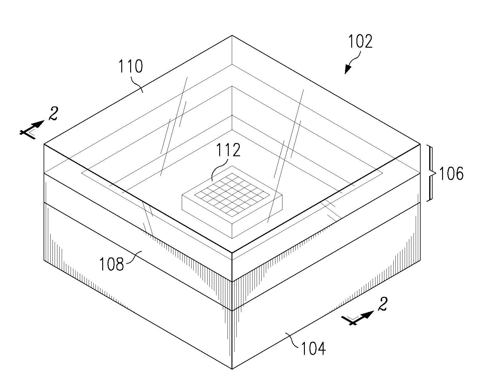
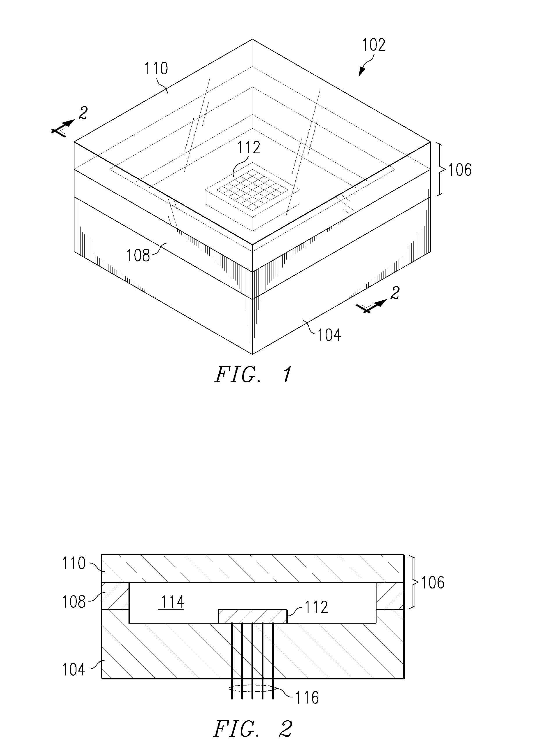
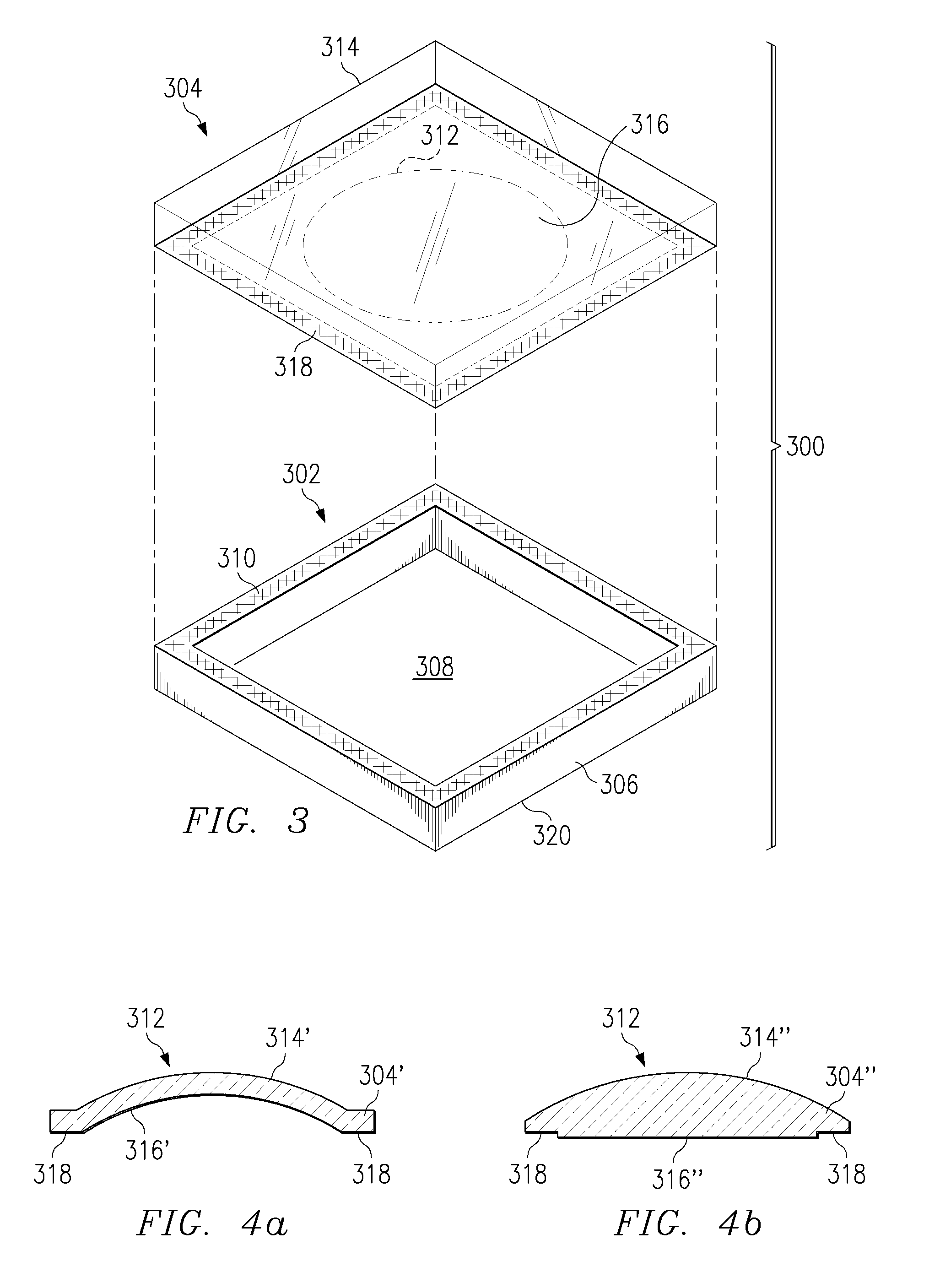
A hermetically sealed multi-pane window assembly comprises first and second windowpane sheets formed of transparent materials. A first sealing member has an inner edge and an outer edge, the inner edge being hermetically attached around the periphery of the first windowpane sheet by diffusion bonding. A second sealing member has an inner edge and an outer edge, the inner edge being hermetically attached around the periphery of the second windowpane sheet by diffusion bonding and the outer edge being hermetically attached to the outer edge of the first sealing member. A spacer assembly is disposed between the first and the second windowpane sheets for maintaining a gap therebetween, whereby a hermetically sealed cavity is defined between the first and the second windowpanes.
Description
CROSS REFERENCE TO RELATED APPLICATIONS [0001] This application is a Continuation-In-Part of pending U.S. application Ser. No. 10 / 766,493 (Dkt. No. STRK-26,581) filed Jan. 27, 2004, which is a Continuation-In-Part of U.S. application Ser. No. 10 / 713,475 (Dkt. No. STRK-26,032) filed Nov. 14, 2003, now U.S. Pat. No. 6,962,834, which is a Continuation-In-Part of U.S. application Ser. No. 10 / 133,049 (Dkt. No. STRK-26,033) filed Apr. 26, 2002, now U.S. Pat. No. 6,723,379, which is a Continuation-In-Part of U.S. application Ser. No. 10 / 104,315 (Dkt. No. STRK-25,911) filed Mar. 22, 2002, now U.S. Pat. No. 6,627,814. This application also claims the benefit of priority from U.S. Provisional Application No. 60 / 678,570 (Dkt. No. STRK-27,067), filed May 6, 2005, and from U.S. Provisional Application No. 60 / 707,367 (Dkt. No. STRK-27,275), filed Aug. 11, 2005.TECHNICAL FIELD OF THE INVENTION [0002] The current invention relates to thermally insulated building windows, and more particularly to mu...
Claims
Login to View More Application Information
Patent Timeline
 Patent Type & AuthorityApplications(United States)
IPC IPC(8): H01H47/18
CPCC03C27/08E06B3/66342H01L21/50H01L23/10H01L27/14618H01L2924/09701H01L2924/0002H01L2924/00
InventorSTARK, DAVID H.
OwnerASTRAVAC GLASS INC