
Fluid heater

a heater and flue technology, applied in the field of flue heaters, can solve problems such as failure, catastrophic failure, and difficulty in controlling in practi

Inactive Publication Date: 2006-08-24
GREEN WEEDER HLDG
View PDF12 Cites 12 Cited by
  • Summary
  • Abstract
  • Description
  • Claims
  • Application Information

AI Technical Summary

Benefits of technology

[0016] In a first aspect the invention provides a fluid heater capable of heating a flow of fluid to a desired temperature, said fluid heater having a fluid inlet for connection to a source of fluid, fluid heating means connected to the inlet, and an outlet for delivering heated fluid supplied by the fluid heating means, wherein there is a temperature controlled pressure regulating valve between the inlet and the outlet, the temperature controlled pressure regulating valve having flow restriction means capable of regulating the flow of heated fluid delivered to the outlet, and heat exchange means allowing the temperature controlled pressure regulating valve to be in heat exchange with the fluid heating means or with the heated fluid leaving the fluid heating means, such that heating or cooling of the temperature controlled pressure regulating valve will cause the flow restriction means to open or close to allow an increase or decrease in the flow of heated fluid leaving the outlet, to thereby control the temperature of the heated fluid leaving the outlet.
[0051] Preferably a thermal cut out device is mounted on the heat sink, and helps to eliminate elements from burning out in the event that fluid was no longer present.

Problems solved by technology

U.S. Pat. No. 2,287,974 describes a continuous hand held water heater, however it has no temperature control other than manual flow control and would appear to be sensitive to air bubbles.
This patent which is owned by the Applicant, describes a product which has been sold under the trade mark GREEN WEEDER and whilst the product works, it is difficult to control in practice.
By using a switched mode power supply, the microprocessor requires the power supply to be interrupted for a number of cycles whilst the element is heating up, thereby creating a lag in the heating process, but more importantly the design of this portable water heater meant that it could fail catastrophically if the water supply from a garden hose was interrupted, by a kink in the hose, or if the end of the wand was raised above horizontal, creating an airlock within the heated pathway inside the wand.
This often resulted in a significant “hot spot” in the conduit and overheating of the element leading to element failure.
If water flow recommenced the water would be super-heated by this “hot spot” creating a blast of steam, which would often result in the steam pressure blowing off the connecting fittings, and thereby interrupting the supply of water, and if the power was not turned off quickly enough the heating element would burn out.
Many experiments by the inventors of the present invention have shown that a real-time heating element controlled by a microprocessor, and accepting water from a garden hose with varying pressures, flow rates, and endeavouring to maintain the temperature of the output water at or close to boiling point of water is very difficult, if not impossible to achieve with modern day electronics within the cost envelope permitted for the manufacture of a portable garden tool.
However it is difficult to cope with air bubbles and varying water pressures and varying input water temperatures in this way, since the range of possible flows is too great.
More importantly even the best thermal sensors have a response time measured in seconds so that the reaction time of the feedback loop is limited primarily by the response time of the thermal sensors.
In most cases providing an average temperature of say 40 degrees Celsius plus / minus 20 degrees Celsius is not acceptable.
It is even worse if the output temperature has to be held at or about 100 degrees Celsius as is the case in vegetation control as 80 degrees Celsius is too cool to kill most weeds, and 120 degrees Celsius will result in the generation of too much steam and the likely failure of the device.
None of these heaters are capable of supplying water at a constant temperature if there are changes in the water supply pressure or input flow rate or input temperature.

Method used


Image

  • Fluid heater
  • Fluid heater
  • Fluid heater

Examples


example 1

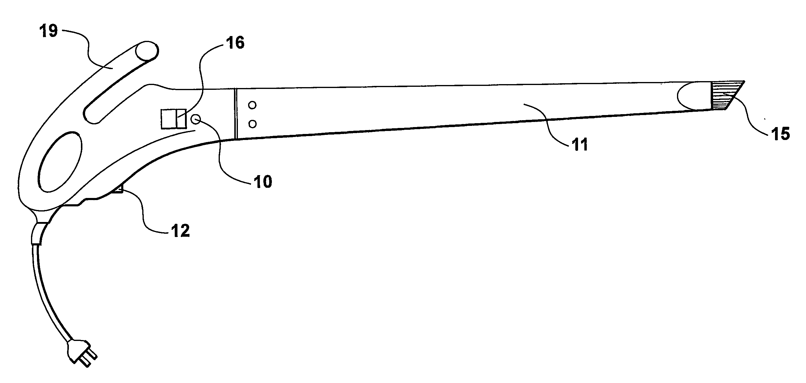
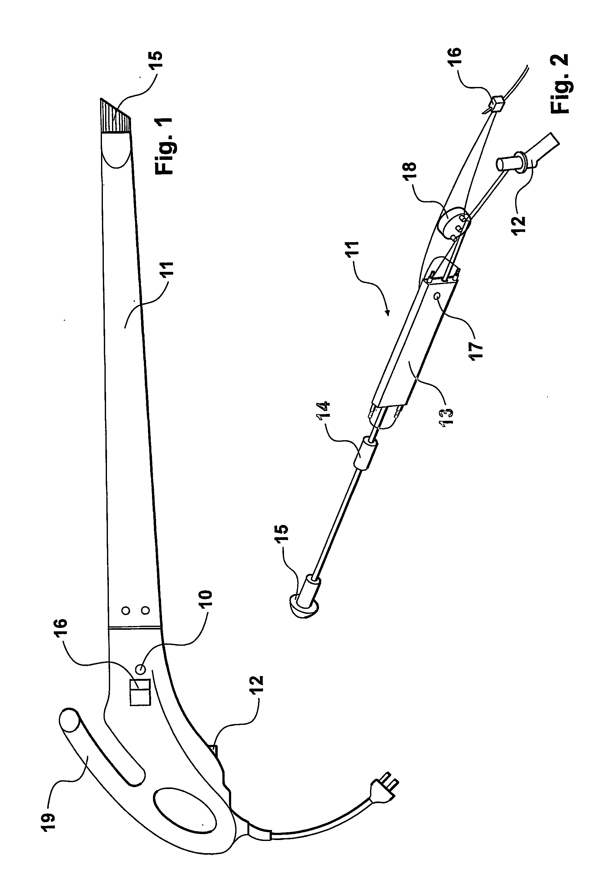
[0066]FIG. 1 shows the assembled weed killer in the form of a hand tool comprising a wand 11 of about 1 metre in length, having a substantially oval cross section through its main length of approximately 100 mm along the long axis and 50 mm along the transverse short axis, with a handle at the top of the wand to which a garden hose can be connected at fitting 12, and from which a power cord extends from the base of the handle. Within the hollow body of the wand 11 there is an electrically powered heater which will be described in more detail below. An on-off switch 16 and power indicating light 10 are provided on the handle.

[0067] In use the wand 11 is connected to a supply of water via a garden hose, and the power cord is connected to (in this case) an extension lead, to mains supply. In its most preferred form the power supply would be capable of supplying from 2 kW to about 2.4 kW, for example in New Zealand this would be a 240 volt power supply at 10 amps, and in North America ...

example 2

Element Heat Sink Assembly

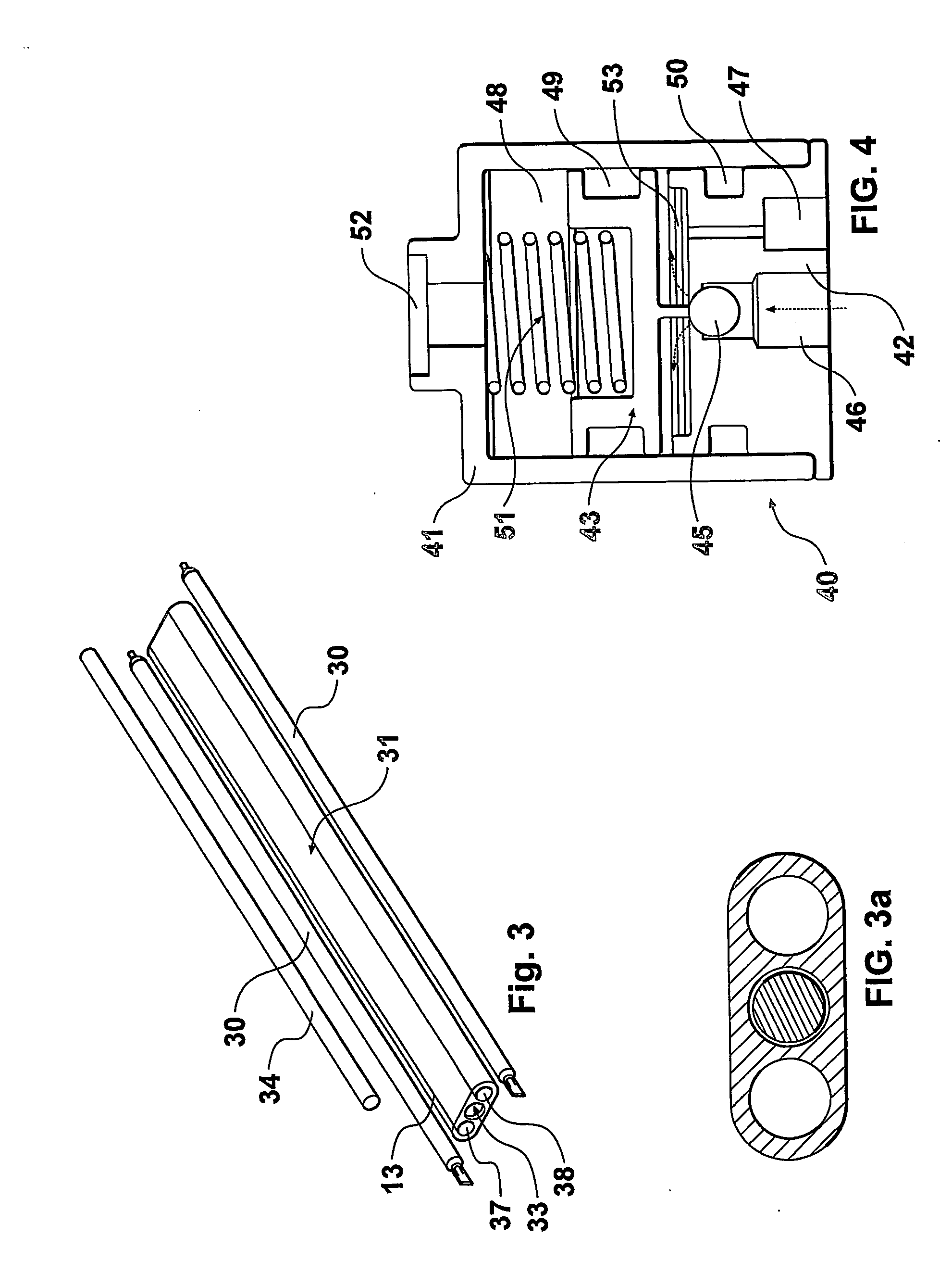
[0090] The heater 13 has a heat sink assembly designed to raise the water temperature from an input temperature of approximately 10-20 degrees Celsius to about 100 degrees Celsius, in this instance, for the DIY market in the eradication of weeds and other undesirable plants. In fact, most prototypes of this invention provided an output of pressurised hot water at about 107 degrees Celsius (plus / minus 1 degree Celsius).

[0091] This is achieved by inserting standard bar electric resistance heating elements 30 (FIG. 3) into a block of aluminium 31 constituting a heat sink and providing a duct 33 for the water to pass through, in the same block.

[0092] Preferably a pair of electric heating elements are provided, so that for a 240 volt power supply the elements can be wired in series, and in the case of 110 volt power supply the elements can be wired in parallel. Alternatively the aluminium block may be longer, with a single heat element, or may be a more compl...

example 3

Thermal Pressure Regulator

[0118] The valve shown in FIG. 3 as flow control valve 14 is preferably a specially designed thermal pressure regulator. A first prototype thermal pressure regulator used a piston, the movement of which is controlled by the temperature response of the vapour pressure of a liquid; in this case the preferred liquid is water, which turns to steam at 100 degrees Celsius, at atmospheric pressure. It will be appreciated that the nature of the liquid can be varied, depending upon the temperature at which the valve is designed to open. This example is concerned with a piston valve, but other types of valves can be designed to use the vapour pressure principle.

[0119] The thermal Pressure regulator as fitted to the weed killer is a special low-pressure water regulator 40 using vapour pressure to control the temperature of the outgoing water. It differs from other pressure regulators by having a sealed pressure chamber in which a small amount of water (or other liqu...


PUM


Abstract

A portable fluid heating tool capable of heating a flow of water under mains pressure to about 107 degrees Celsius and has a connection to a water supply via a hose. Water flows through an electrical heater within the tool, then to a thermally controlled pressure regulating valve (80) and then to the outlet nozzle. This valve (80) has a moveable member such as a diaphragm (83) sealing off a pressure chamber (88). Movement of the diaphragm (83) causes a valve (85) to open or at least partly close. When closed the valve (85) impedes, or restricts the flow of water from an inlet (86) to an outlet (87) through the valve. On the other side of the diaphragm a small quantity of water is trapped within the pressure chamber (88), so that as the valve (80) heats up, pressure within the pressure chamber (88) rises as the water turns to water vapour and the air within the chamber also expands. This increase in pressure within the pressure chamber (88) causes the diaphragm (83) to move slightly outwardly causing a pintle (84) to allow the ball valve (85) to open and allow maximum flow of the heated water through the valve (80) to the nozzle of the tool.

Description

FIELD OF THE INVENTION [0001] This invention relates to a fluid heater and in particular to a portable fluid heater in the form of a hand tool for electrically heating water to a temperature suitable for use in killing vegetation (primarily weeds) or clearing ant's nests. To do this it is preferable that the water is heated in a continuous stream to a temperature at or near its boiling point. BACKGROUND [0002] A requirement exists for supplying a continuous stream of water at a controlled temperature. One such application is a source of near boiling water in a portable form for use in killing weeds or ant nests, for heating the skin of dead animals so that feathers or hair can be stripped, for wallpaper stripping or for similar purposes. Another application is the provision of water at a substantially constant temperature for washing purposes, e.g. for washing clothes, dishes or hands or in a shower where the temperature should be controlled within plus / minus 1 degree Celsius regard...

Claims


Application Information

Patent Timeline
Patent Type & Authority Applications(United States)
IPC IPC(8): F24H1/10B05B1/24B05B7/22B67D5/62A01M1/20A01M19/00A01M21/04B05B9/00B05B9/01B67D7/80F16K31/64F16K31/68F24H1/14
CPCA01M1/2094A01M3/007A01M19/00A01M21/04A01M2200/011B05B9/002B05B9/01F24H1/142
Inventor HIGHAM, ANTHONY J.CLARK, PETER BRUDETAIT, BRENDON
Owner GREEN WEEDER HLDG
Learn More