
Method and apparatus for determining an improved assist feature configuration in a mask layout

a mask and configuration technology, applied in the field of semiconductor manufacturing, can solve the problems of difficult management, preventing designers from being able to achieve the best device performance, and missing or suboptimal placement and/or dimensioning of assist features, so as to improve the manufacturability of the mask layout and reduce the computational time

Active Publication Date: 2006-08-24
SYNOPSYS INC
View PDF41 Cites 23 Cited by
  • Summary
  • Abstract
  • Description
  • Claims
  • Application Information

AI Technical Summary

Benefits of technology

[0011] One embodiment of the present invention provides a system that determines the locations and dimensions of one or more assist features in an uncorrected or corrected mask layout. During operation, the system receives a mask layout. The system then creates a set of candidate assist feature configurations, which specify locations and dimensions for one or more assist features in the mask layout. Next, the system determines an improved assist feature configuration using the set of candidate assist feature configurations and a process-sensitivity model which can be represented by a multidimensional function that captures process-sensitivity information. Note that placing assist features in the mask layout based on the improved assist feature configuration improves the manufacturability of the mask layout. Moreover, using the process-sensitivity model to determine the improved assist feature configuration reduces the computational time required to determine the improved assist feature configuration in the mask layout.
[0014] Another embodiment of the present invention provides a system that determines the dimensions of one or more assist features in an uncorrected or corrected mask layout. During operation, the system receives a set of assist features located in a 2-D region of the mask layout. The system then creates a set of candidate assist feature configurations, which specify the dimensions for one or more assist features in the set of assist features. Next, the system determines an improved assist feature configuration using the set of candidate assist feature configurations and a process model that models one or more semiconductor manufacturing processes. Note that dimensioning assist features in the mask layout based on the improved assist feature configuration improves the manufacturability of the mask layout. Moreover, using the process-sensitivity model to determine the improved assist feature configuration reduces the computational time required to determine the improved assist feature configuration in the mask layout.

Problems solved by technology

Furthermore, rule-based approaches can result in missed or sub-optimal placement and / or dimensioning of assist features.
Additionally, large and complex layouts can require a large number of design rules, which can be very difficult to manage.
Moreover, design rules can be overly restrictive which can prevent designers from being able to achieve the best device performance.
As a result, rule-based techniques are usually not effective for improving the depth of focus of 2-D regions in a pattern.
Moreover, using the process-sensitivity model to determine the improved assist feature configuration reduces the computational time required to determine the improved assist feature configuration in the mask layout.

Method used


Image

  • Method and apparatus for determining an improved assist feature configuration in a mask layout
  • Method and apparatus for determining an improved assist feature configuration in a mask layout
  • Method and apparatus for determining an improved assist feature configuration in a mask layout

Examples


Embodiment Construction

Integrated Circuit Design and Fabrication

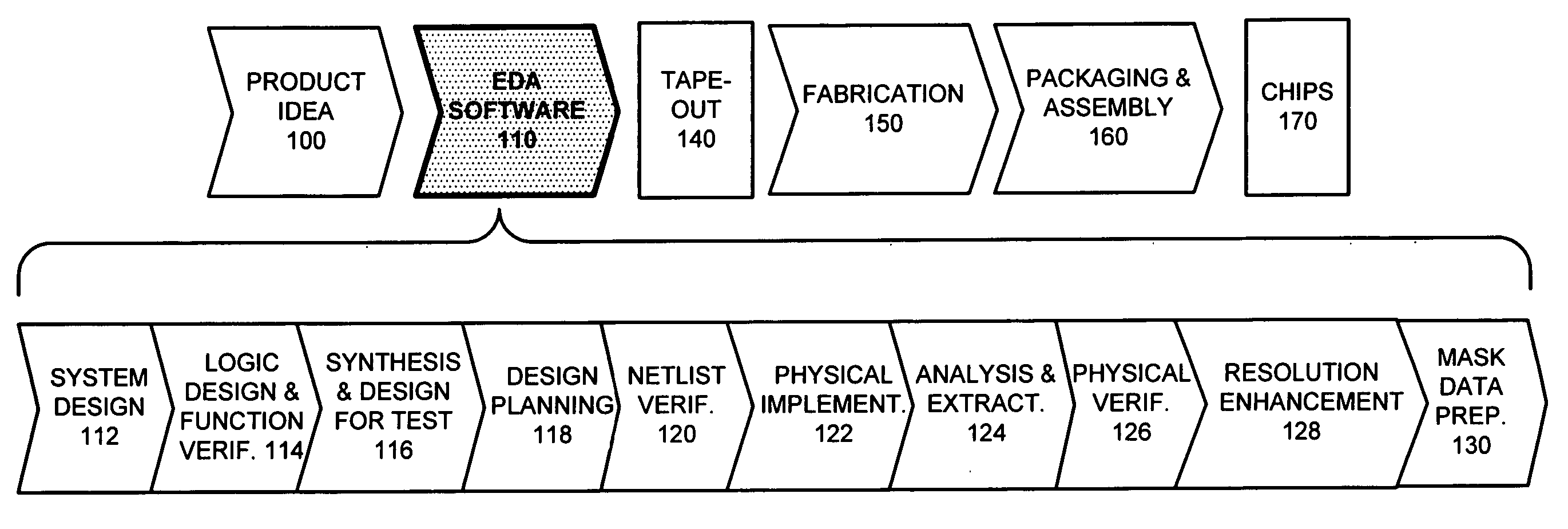
[0026]FIG. 1 illustrates various steps in the design and fabrication of an integrated circuit in accordance with an embodiment of the present invention. The process starts with a product idea (step 100). Next, the product idea is realized using an integrated circuit, which is designed using Electronic Design Automation (EDA) software (step 110). Once the circuit design is finalized, it is taped-out (step 140). After tape-out, the process goes through fabrication (step 150), packaging, and assembly (step 160). The process eventually culminates with the production of chips (step 170).

[0027] The EDA software design step 110, in turn, includes a number of sub-steps, namely, system design (step 112), logic design and function verification (step 114), synthesis and design for test (step 116), design planning (step 118), netlist verification (step 120), physical implementation (step 122), analysis and extraction (step 124), physical verification ...


PUM

PropertyMeasurementUnit
dimensionsaaaaaaaaaa
semiconductoraaaaaaaaaa
optical image intensity modelaaaaaaaaaa

Abstract

One embodiment of the present invention provides a system that determines the locations and dimensions of one or more assist features in an uncorrected or corrected mask layout. During operation, the system receives a mask layout. The system then creates a set of candidate assist feature configurations, which specify locations and sizes for one or more assist features in the mask layout. Next, the system determines an improved assist feature configuration using the set of candidate assist feature configurations and a process-sensitivity model which can be represented by a multidimensional function that captures process-sensitivity information. Note that placing assist features in the mask layout based on the improved assist feature configuration improves the manufacturability of the mask layout. Moreover, using the process-sensitivity model to determine the improved assist feature configuration reduces the computational time required to determine the improved assist feature configuration in the mask layout.

Description

RELATED APPLICATION [0001] This application is a continuation-in-part of, and hereby claims priority under 35 U.S.C. § 120 to, U.S. patent application Ser. No. 11 / 065,409, entitled, “METHOD AND APPARATUS FOR IDENTIFYING A MANUFACTURING PROBLEM AREA IN A LAYOUT USING A PROCESS-SENSITIVITY MODEL,” by inventors Lawrence S. Melvin III and James P. Shiely filed on 24th Feb. 2005 (Attorney Docket No. SNPS-0641). BACKGROUND [0002] 1. Field of the Invention [0003] The present invention is related to semiconductor manufacturing. More specifically, the present invention is related to a method and apparatus for determining an improved assist feature configuration in a mask layout using a process-sensitivity model. [0004] 2. Related Art [0005] The dramatic improvements in semiconductor integration densities in recent years have largely been made possible by corresponding improvements in semiconductor manufacturing technologies. [0006] One such semiconductor manufacturing technology involves pla...

Claims


Application Information

Patent Timeline
Patent Type & Authority Applications(United States)
IPC IPC(8): B28B11/00
CPCG03F1/144G03F1/36Y10T428/131G03F7/705G03F7/70433G03F1/70
Inventor MELVIN, LAWRENCE S. IIIPAINTER, BENJAMIN D.
Owner SYNOPSYS INC
Features
  • Generate Ideas
  • Intellectual Property
  • Life Sciences
  • Materials
  • Tech Scout
  • Unparalleled Data Quality
  • Higher Quality Content
  • 60% Fewer Hallucinations
Learn More