

Multi-reservoir device for controlled drug delivery
a multi-reservoir device and controlled drug technology, applied in the direction of medical devices, inorganic non-active ingredients, therapy, etc., can solve the problems of clogging, failure of the pump, and the individual's clogging may be catastrophic, and depend on the reliable operation of moving parts
- Summary
- Abstract
- Description
- Claims
- Application Information
AI Technical Summary
Benefits of technology
Problems solved by technology
Method used
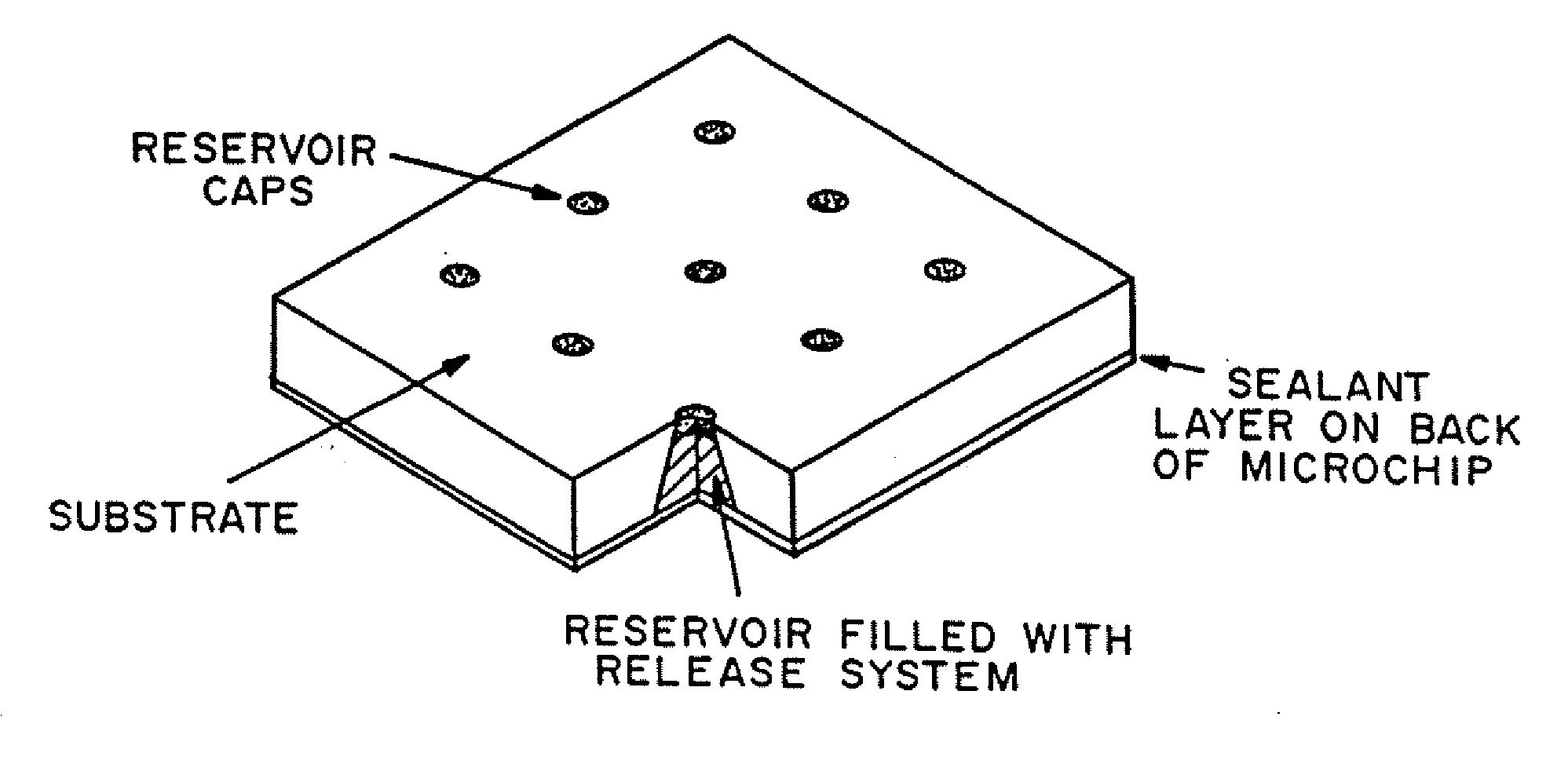
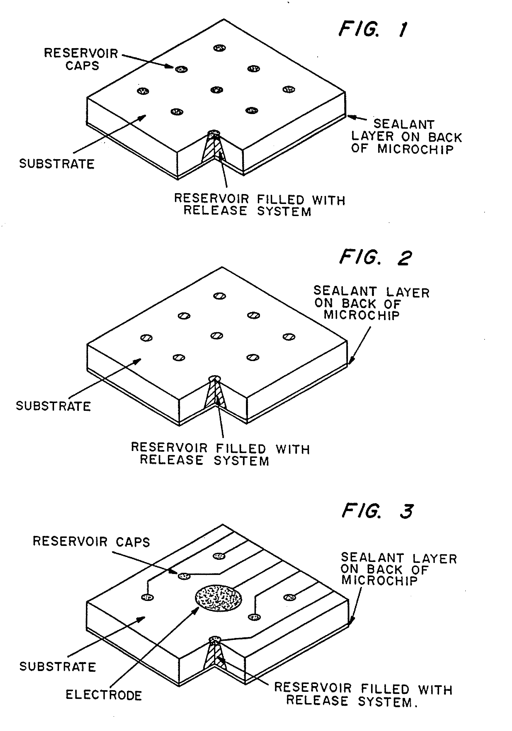
Image

Examples
example 1
Fabrication of Polymeric Microchip Device Having Cholesterol Reservoir Caps
[0086] The following procedure was used to produce a polymeric microchip device having cholesterol reservoir caps for passive release.
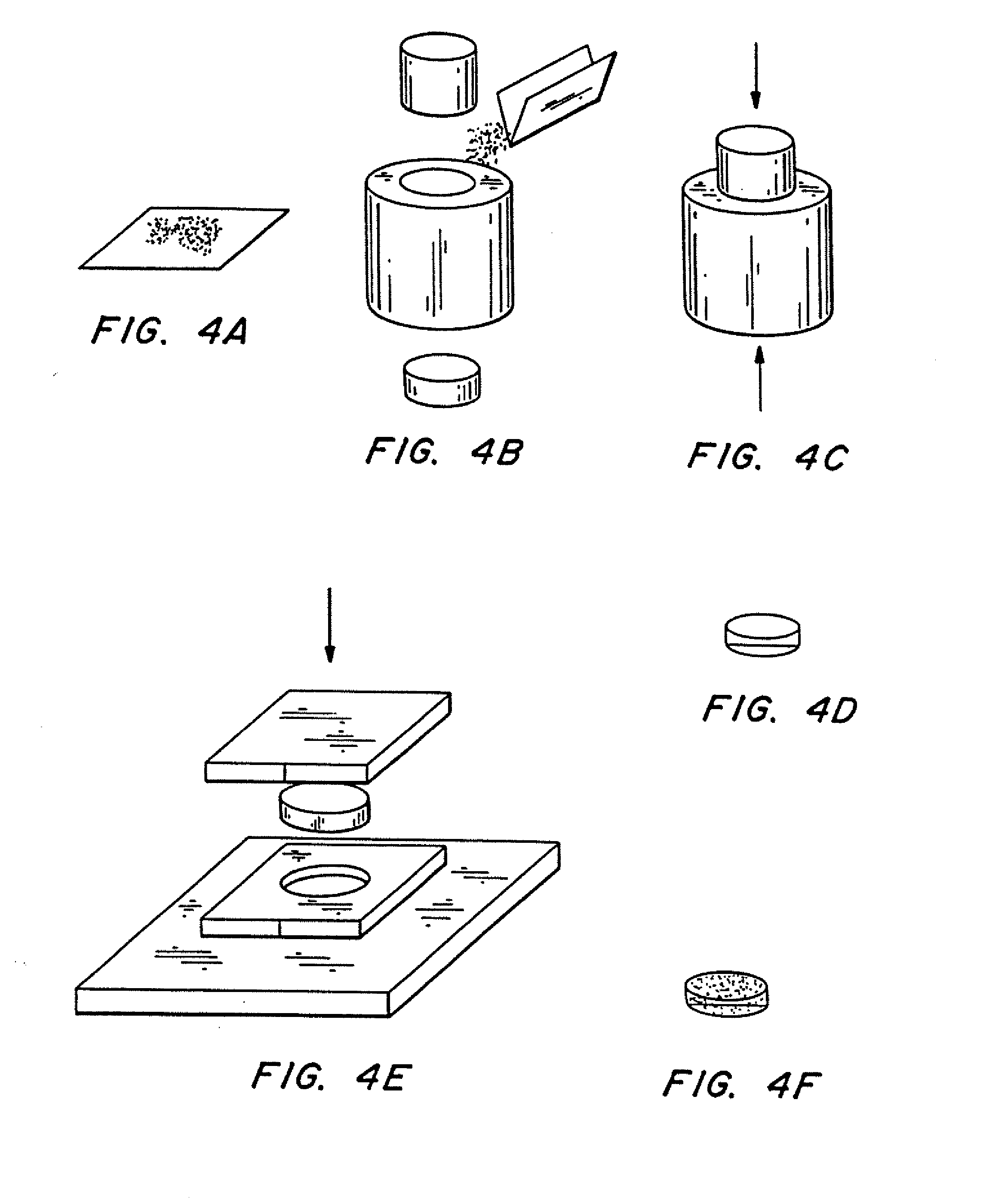
(1) Weighed 0.4 g of poly(lactic-co-glycolic acid) powder, molecular weight ˜25,000 powder (see FIG. 4a).
(2) Inserted bottom piston into conical steel die. 1.27 cm (½″) in diameter, filled with polymer powder from step (1), and inserted top piston into die (see FIG. 4b).
(3) Put the die with powder into Carver Laboratory Press, model C. Pressed at room temperature for one minute and thirty seconds at approximately 69×106 Pa (10,000 psi), yielding a cylindrical polymer preform (see FIG. 4c).
(4) Removed cylindrical polymer preform from the die (see FIG. 4d).
[0087] (5) Placed cylindrical polymer preform into aluminum die plate (aluminum sheet, approximately 3 mm (or ⅛″) thick, with a hole of approximately the same diameter as the polymer preform). Allowed die plate to res...
example 2
Fabrication of Polymeric Microchip Device Having Cholesterol / Lecithin Reservoir Caps
[0093] The following alternative procedure was used to produce a polymeric microchip device having cholesterol / lecithin reservoir caps for passive release.
(1)-(4) Followed steps (1) through (4) described in Example 1 to form a polymer preform.
[0094] (5) Placed cylindrical polymer preform into aluminum die plate (aluminum sheet, approximately 3 mm (or ⅛″) thick, with a hole of approximately the same diameter as the polymer preform). Allowed die plate to rest on aluminum plate having conical indenters, and covered top with another aluminum plate, 3 mm (or ⅛″) thick.
[0095] (6) Placed the assembly from (5) into Carver Laboratory Press, model C, at 54° C. (130° F.). Set temperature of heated platens to 54° C. (130° F.). The load pressure remained at approximately 8896 N (2000 pounds-force). The assembly was left in the lab press for approximately ten minutes. A hole machined in the side of the indent...
example 3
Fabrication of Polymeric Microchip Device Having Polymeric Reservoir Caps
[0098] The following procedure was used to produce a polymeric microchip device having polyester reservoir caps for passive release.
(1) Weighed desired amount of a polymer powder (see FIG. 4a). Here, 0.4 g of poly(lactic acid) (MW approximately 100,000) was used.
(2) Inserted bottom piston into conical steel die , 1.27 cm (½ inch) in diameter, filled die with polymer powder from step (1), and inserted top piston into die (see FIG. 4b).
(3) Placed the die with powder into Carver Laboratory Press, model C. Pressed at room temperature for one minute and thirty seconds at approximately 69×106 Pa (10,000 psi), yielding a cylindrical polymer preform (see FIG 4c).
(4) Removed cylindrical polymer preform from the die (see FIG. 4d).
[0099] (5) Placed polymer preform on aluminum die plate containing an array of indenters for forming the reservoirs in the polymeric substrate. An aluminum plate 3 mm thick, with a 1.2...
PUM
 Abstract
Description
Claims
Application Information