Hands-free bail-elevator locking device with combined power/control connector, bail spreader and method for use

Inactive Publication Date: 2006-08-31
BLOHM VOSS REPAIR
View PDF23 Cites 42 Cited by
  • Summary
  • Abstract
  • Description
  • Claims
  • Application Information

AI Technical Summary

Benefits of technology

[0012] A primary object of the invention is to provide a method and apparatus for increasing the efficienc

Problems solved by technology

In the prior art, coupling the bails to the elevators is done in a time-consuming labor-intensive manual process.
Further, each bail must be securely fixed to the corresponding elevator ear, requiring another time-consuming step in the rigging process of manually engaging a locking device.
When ci

Method used


Image

  • Hands-free bail-elevator locking device with combined power/control connector, bail spreader and method for use
  • Hands-free bail-elevator locking device with combined power/control connector, bail spreader and method for use
  • Hands-free bail-elevator locking device with combined power/control connector, bail spreader and method for use

Examples


Embodiment Construction

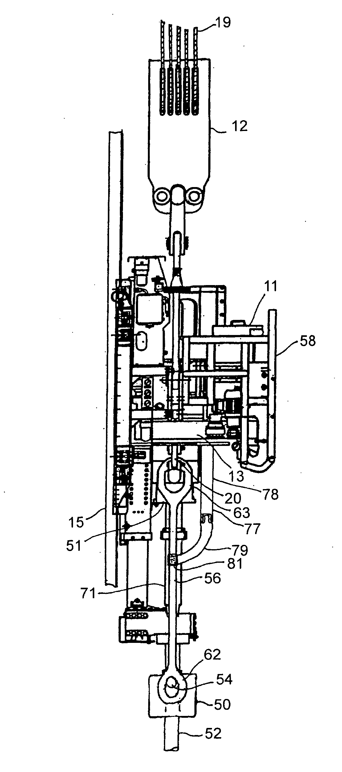
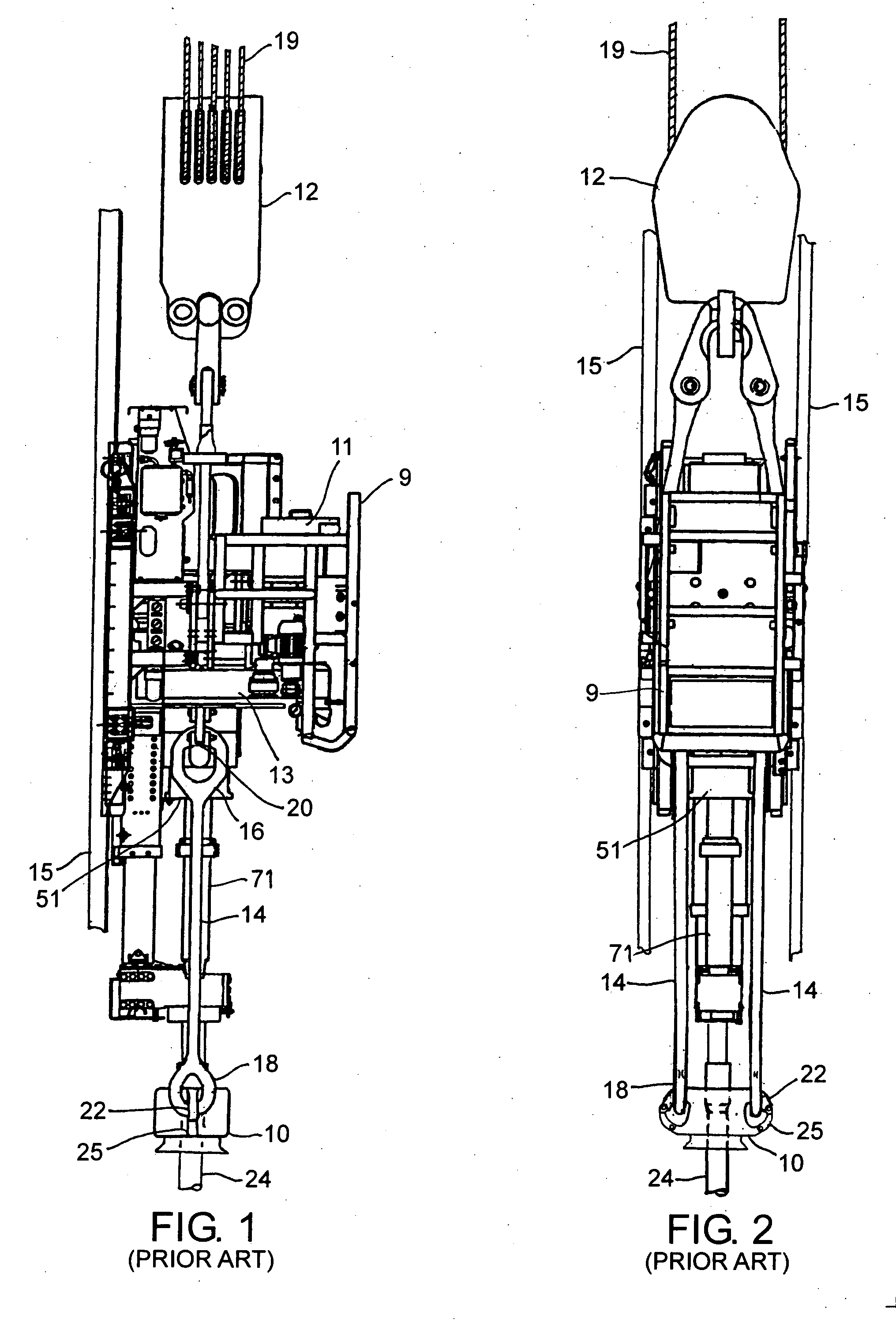
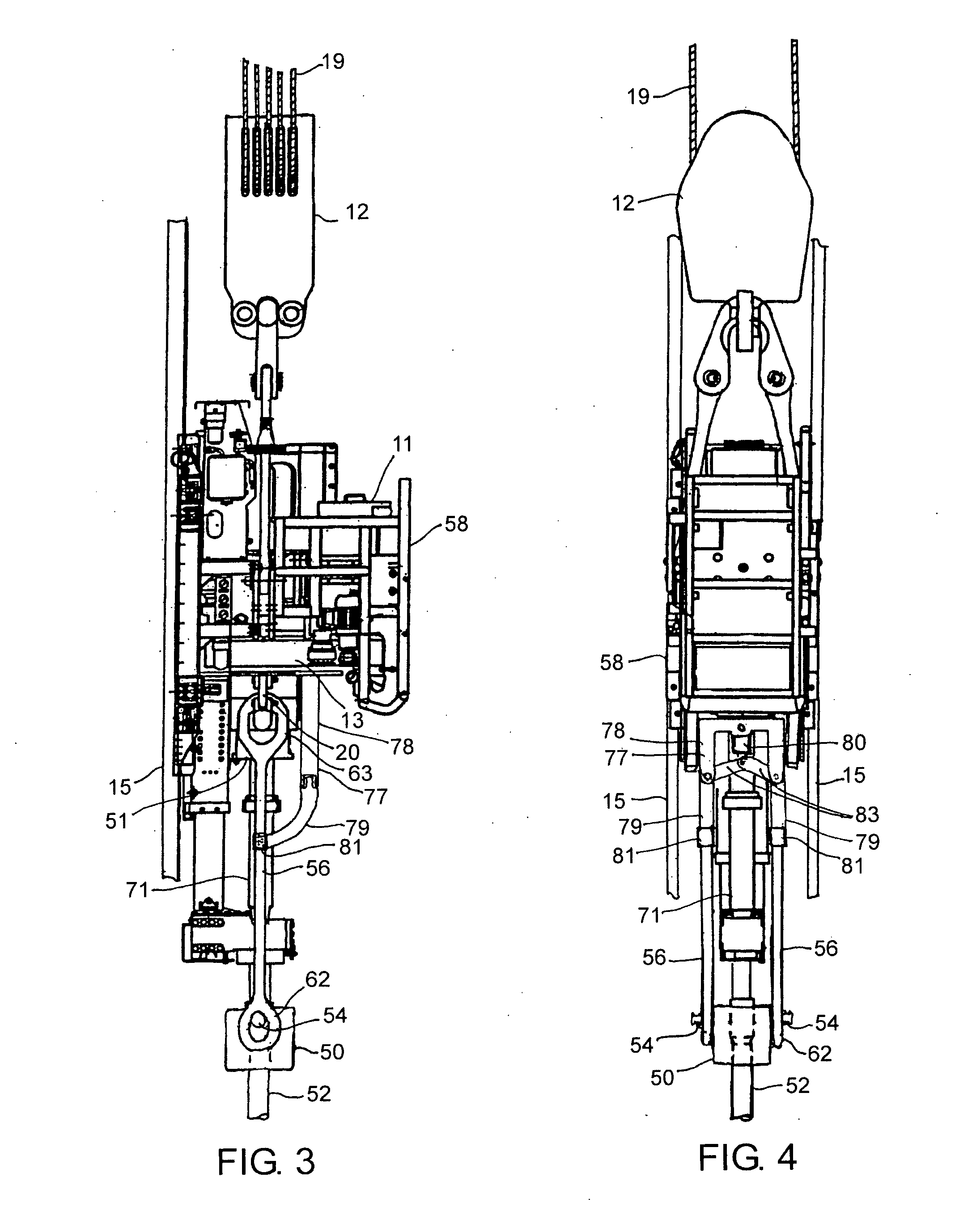
[0042]FIGS. 3-5 illustrate a top drive mechanism 58 according to one embodiment of the invention equipped with a link spreader mechanism 78 for hands-free movement of the suspended links 56. Top drive 58 is similar to the prior art top drive 9 of FIGS. 1-2, preferably having a motor 11, gear train 13, link supports 20, and sliding frame members 15. Additionally, the top drive 58 may include an air cooling system (not shown), a rotary hose connection (not shown), a rotary manifold (51), and a lower well control valve (71). As these top drive features are well known in the art, they are not discussed further herein. The link spreader mechanism 78 is ideally disposed at the lower portion of the top drive 58 near the link supports 20. The link spreader mechanism 78 preferably includes an inverted generally U-shaped frame 77 with each distal end of frame 77 acting as a fulcrum for a rigidly connected curved control arm 79 / lever 83 pair. The distal end of each curved control arm 79 is cou...


PUM


Abstract

A method and apparatus for raising or lowering a tubular in a well wherein bails are conventionally coupled to elevator ears and locking assemblies secured to the outer sides of the lower bail eyes for remote controlled clamping to nipples integral with and extending from the elevator ears. The locking assemblies contain upper and lower jaws which, by a remotely controlled actuator, move in linear relation to each other and have concave clamping surfaces which join together to form a circular opening for receiving the elevator ear nipples. The nipples have enlarged diameters at their distal ends to prevent removal from the closed jaws. A remotely controlled link spreading mechanism spreads the bails to accommodate an elevator. Elevator ears may contain internal conduits for communication of power and control signals between the suspended elevator and the bails. The passages mate with a remotely actuated connector assembly.

Description

BACKGROUND OF THE INVENTION [0001] 1. Field of the Invention [0002] This invention relates generally to drilling equipment used particularly in the hydrocarbon production industry and specifically to a method and apparatus for mechanized coupling and locking of bails to elevator ears and the concomitant coupling of power and control circuits between the bails and the suspended elevator. [0003] 2. Description of the Prior Art [0004] In the hydrocarbon production industry, tubular goods, including drill strings, casings and tubing and often referred to simply as tubulars, must at varying stages be run, i.e. lowered, into or raised from a well. Elevators are devices which support the tubular for the purpose of raising or lowing it. An elevator may clamp along the side of a tubular using slips and dies to exert a radial clamping force on the tubular wall, or an elevator may use a bushing to support the tubular at the lower lip of a box connector. The latter method is preferable for deep...

Claims


Application Information

Patent Timeline
IPC IPC(8): E21B19/18
CPCE21B19/06
Inventor SEVERIN, IWOLUTZHOEFT, JENSGROTHERR, JORN
Owner BLOHM VOSS REPAIR
Why Eureka
Try Eureka