Organic electroluminescent device

an electroluminescent device and organic technology, applied in the direction of discharge tube luminescnet screens, other domestic articles, natural mineral layered products, etc., can solve the problems of slow response to light emission and persisting durability, and achieve the effect of amplifying the intensity of light emission and high degree of efficiency

Active Publication Date: 2006-08-31
UDC IRELAND
View PDF17 Cites 19 Cited by
  • Summary
  • Abstract
  • Description
  • Claims
  • Application Information

AI Technical Summary

Benefits of technology

[0012] It is preferable that the organic electroluminescent device contain a compound, hereinafter, referred to as an “amplifying agent”, which can perform a function of amplifying the number of singlet excitons generated at the time that voltage is applied, and thus amplify the intensity of light emission.
[0013] The invention can provide an organic electroluminescent device that can emit light with a high degree of efficiency.

Problems solved by technology

However, since a phosphorescent light emission from a heavy atomic metal complex is used, the response of light emission has been slow, and an improvement in durability also remains to be desired.

Method used


Image

  • Organic electroluminescent device
  • Organic electroluminescent device
  • Organic electroluminescent device

Examples


example 1

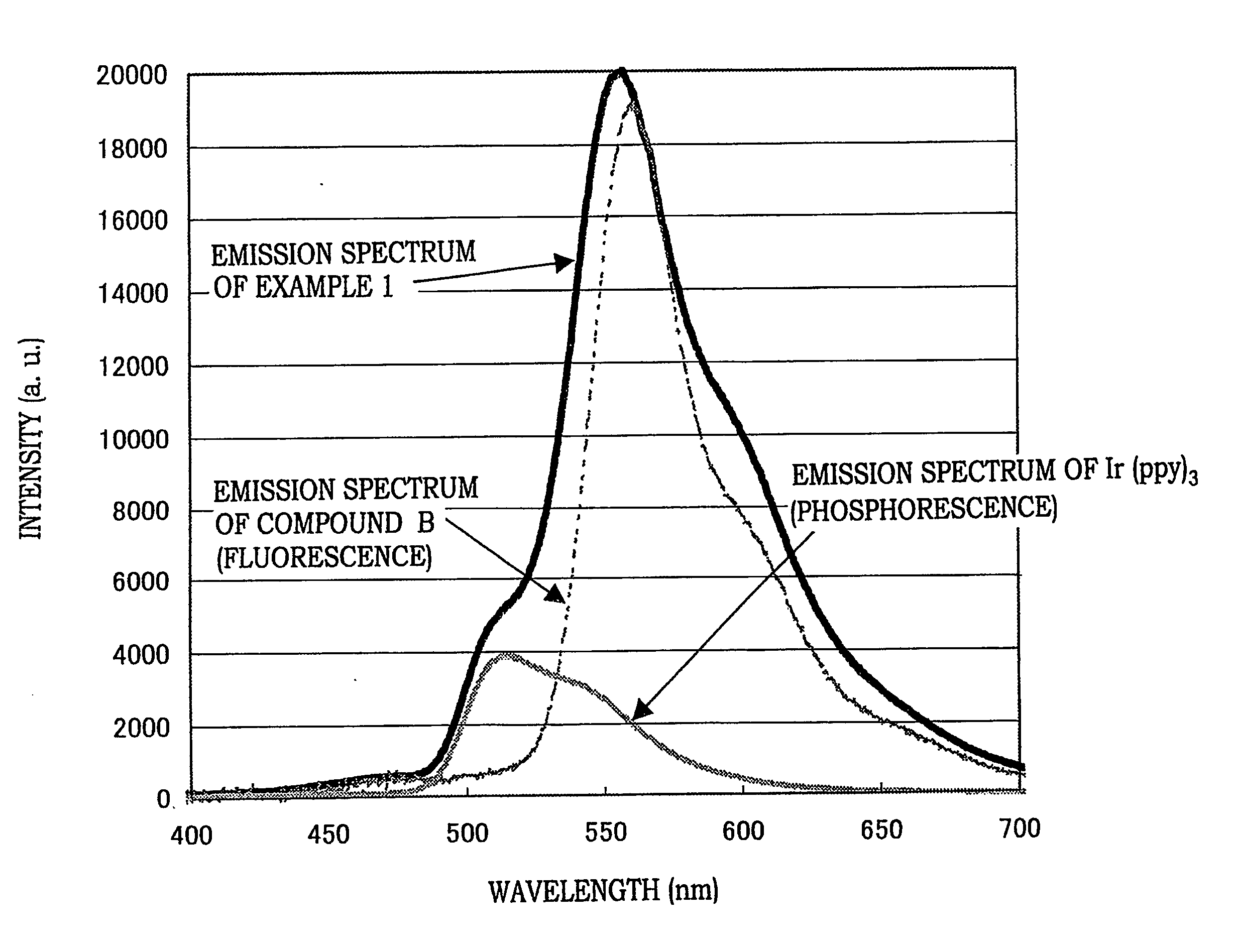
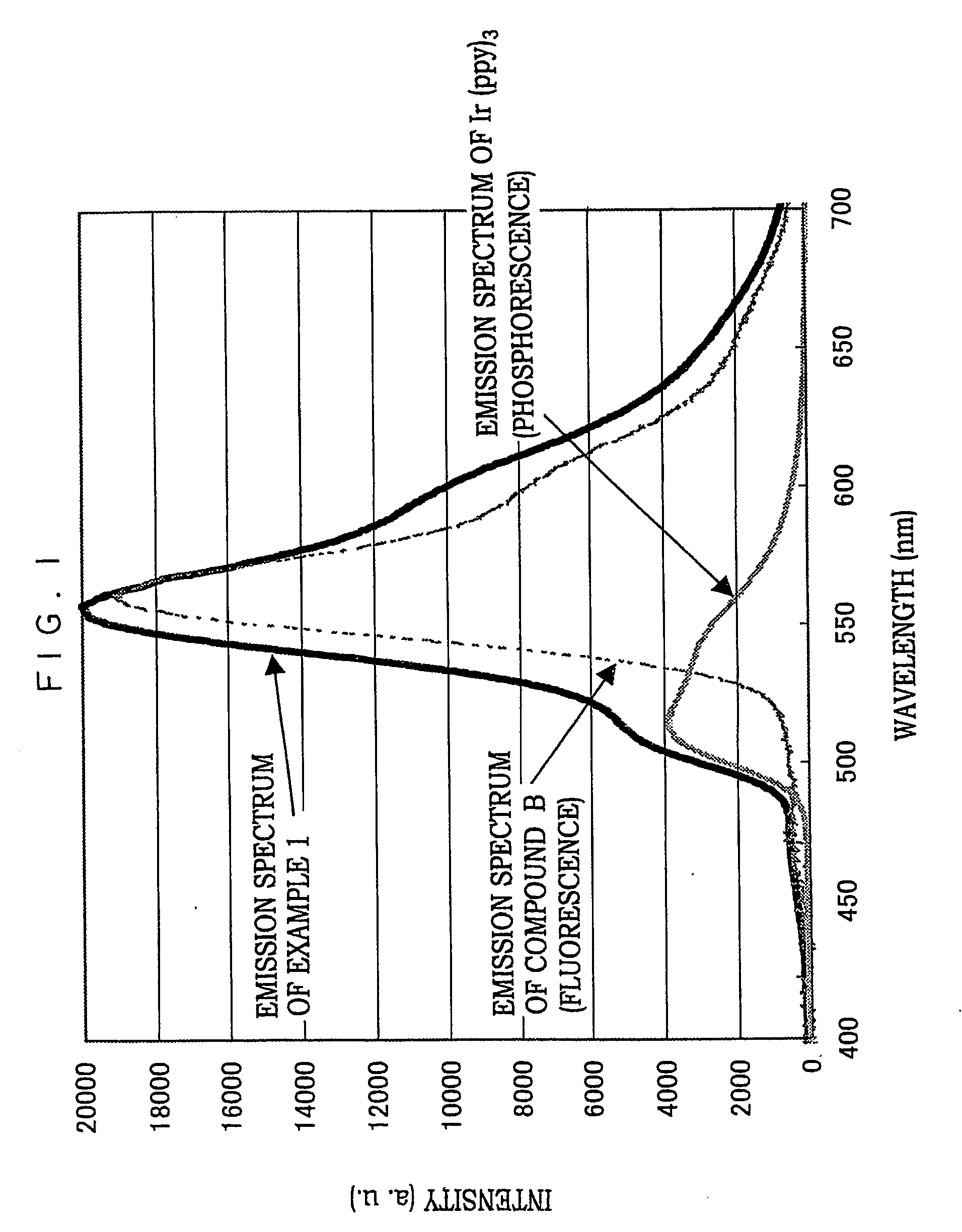
[0183] A cleaned ITO substrate was set in a vacuum deposition apparatus. N,N′-diphenyl-N,N′-di(m-tolyl)benzidine (TPD) was deposited on the substrate to a thickness of 50 nm. Then, a compound A (host material) and a compound B (compound emitting fluorescence) were deposited on the TPD layer in a ratio of 99:1 to a deposition thickness of 1 nm. Then compound A and Ir(ppy)3 (amplifying agent) were deposited on the TPD layer in a ratio of 17:1 to a deposition thickness of 1 nm. This process was repeated 18 times, and an alternate laminated film of 36 nm in total was formed. In this case, a crucible in which compound A and compound B had been poured and a crucible in which compound A and Ir(ppy)3 had been poured were heated to temperatures at which the crucibles could be constantly deposited. Deposition was repeated by the switching of a shutter set in the vicinity of the crucible. A compound C was deposited thereon to a deposition thickness of 36 nm. A pattern mask (having a pattern gi...

example 2

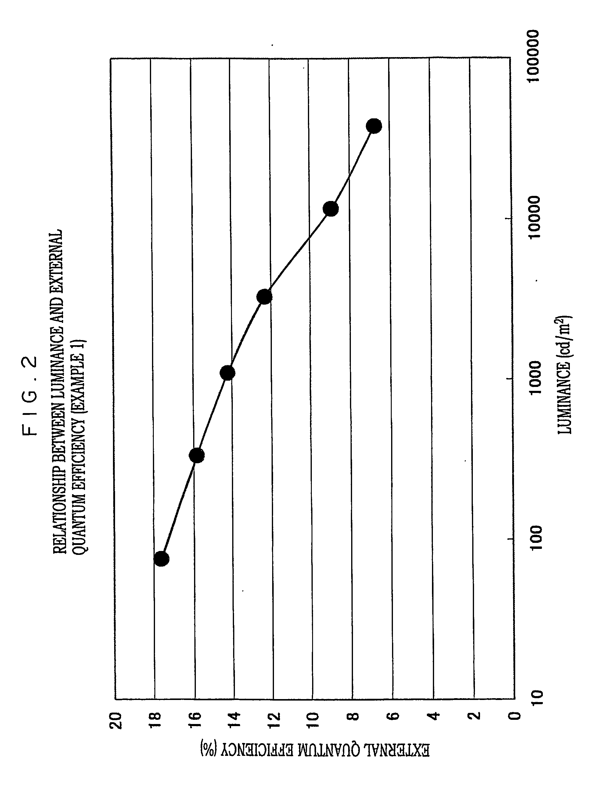
[0184] Alq3 was used in place of compound C in Example 1, and the device was fabricated and tested in the same manner as in Example 1. As a result, the yellow light emission of maximum light-emitting wavelength λ max=565 nm and CIE chromaticity (x,y)=(0.47, 0.51) were obtained, and the external quantum efficiency at 200 cd / m2 was 11.7%. The internal quantum efficiency was calculated to be 58.5%. The light emission was mainly derived from compound B. The proportion accounted for by the fluorescent luminescence of compound B was about 95%. The approximately 5% remaining was accounted for by phosphorescence luminescence derived from Ir (ppy)3.

example 3

[0185] CBP was used in place of compound A in Example 1, and the device was fabricated and tested in the same manner as in Example 1. As a result, the yellow light emission of maximum light-emitting wavelength λ max=550 nm and CIE chromaticity (x,y)=(0.37, 0.56) were obtained, and the external quantum efficiency at 200 cd / m2 was 8.1%. The internal quantum efficiency was calculated to be 40.5%. The light emission was mainly derived from compound B. The proportion accounted for by the fluorescent luminescence of compound B was about 90%. The approximately 10% remaining was accounted for by phosphorescence luminescence derived from Ir(ppy)3.


PUM

PropertyMeasurementUnit
external quantum efficiencyaaaaaaaaaa
internal quantum efficiencyaaaaaaaaaa
light-emitting wavelengthaaaaaaaaaa

Abstract

An organic electroluminescent device having at least one organic layer containing a light-emitting layer between a pair of electrodes, wherein the organic electroluminescent device contains a compound emitting fluorescence at a time that voltage is applied, and the light emission at the time that voltage is applied is mainly derived from the light emission of a fluorescent compound, and the external quantum efficiency of the device is 6% or more. It is preferable that the organic electroluminescent device contain an amplifying agent performing the function of amplifying the number of singlet excitons generated at the time that voltage is applied, thus amplifying the intensity of the light emission. The amplifying agent is a transition metal complex, in particular, an iridium complex, a platinum complex, a rhenium complex, a ruthenium complex, a palladium complex, a rhodium complex, a copper complex or a rare earth device complex. The compound emitting fluorescence is preferably a fused aromatic compound.

Description

BACKGROUND OF THE INVENTION [0001] 1. Technical Field [0002] The present invention relates to a light-emitting device capable of converting electric energy to light, particularly an organic electroluminescent device, hereinafter on occasion referred to as a “device”, a “light-emitting device”, an “EL device” or an “organic EL device”. [0003] 2. Related Art [0004] Organic electroluminescent (EL) devices have been attracting attention as promising display devices for obtaining luminescence of a high intensity at a low driving voltage. An important characteristic value of an organic electroluminescent device is external quantum efficiency. External quantum efficiency is calculated by “external quantum efficiency φ=number of photons discharged from a device / number of electrons injected into a device”. The higher the value of external quantum efficiency, the lower the power consumption of the device, and thereby a device having a higher value of external quantum efficiency is advantageou...

Claims


Application Information

Patent Timeline
Patent Type & Authority Applications(United States)
IPC IPC(8): H05B33/14H01L51/50H01L51/00H01L51/30H05B33/22
CPCH01L51/0051H01L51/0054H01L51/0056H01L51/0058H01L51/006H01L51/0067H01L51/0071H01L51/0077H01L51/0081H01L51/0085H01L51/5012Y10S428/917H10K85/611H10K85/622H10K85/624H10K85/626H10K85/633H10K85/654H10K85/657H10K85/30H10K85/324H10K85/342H10K50/11H05B33/14H10K10/00
Inventor IGARASHI, TATSUYANARIYUKI, FUMITO
Owner UDC IRELAND
Why Eureka
Try Eureka