
Apparatus and method of treating fine powders

a technology of fine powder and apparatus, applied in the field of treatment, can solve the problems of non-uniform compression providing a flow gradient, shear and tensile forces being applied to the particulate material, and achieve the effect of higher relative fracture toughness

Inactive Publication Date: 2006-08-31
ETERNALOY HLDG GMBH
View PDF8 Cites 41 Cited by
  • Summary
  • Abstract
  • Description
  • Claims
  • Application Information

AI Technical Summary

Benefits of technology

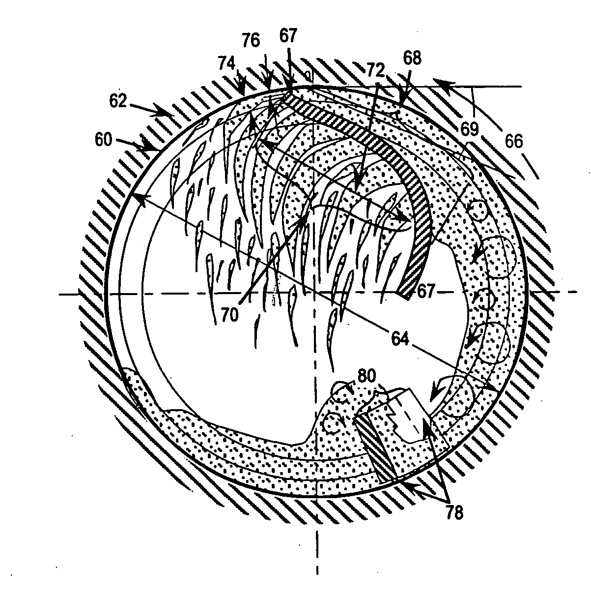
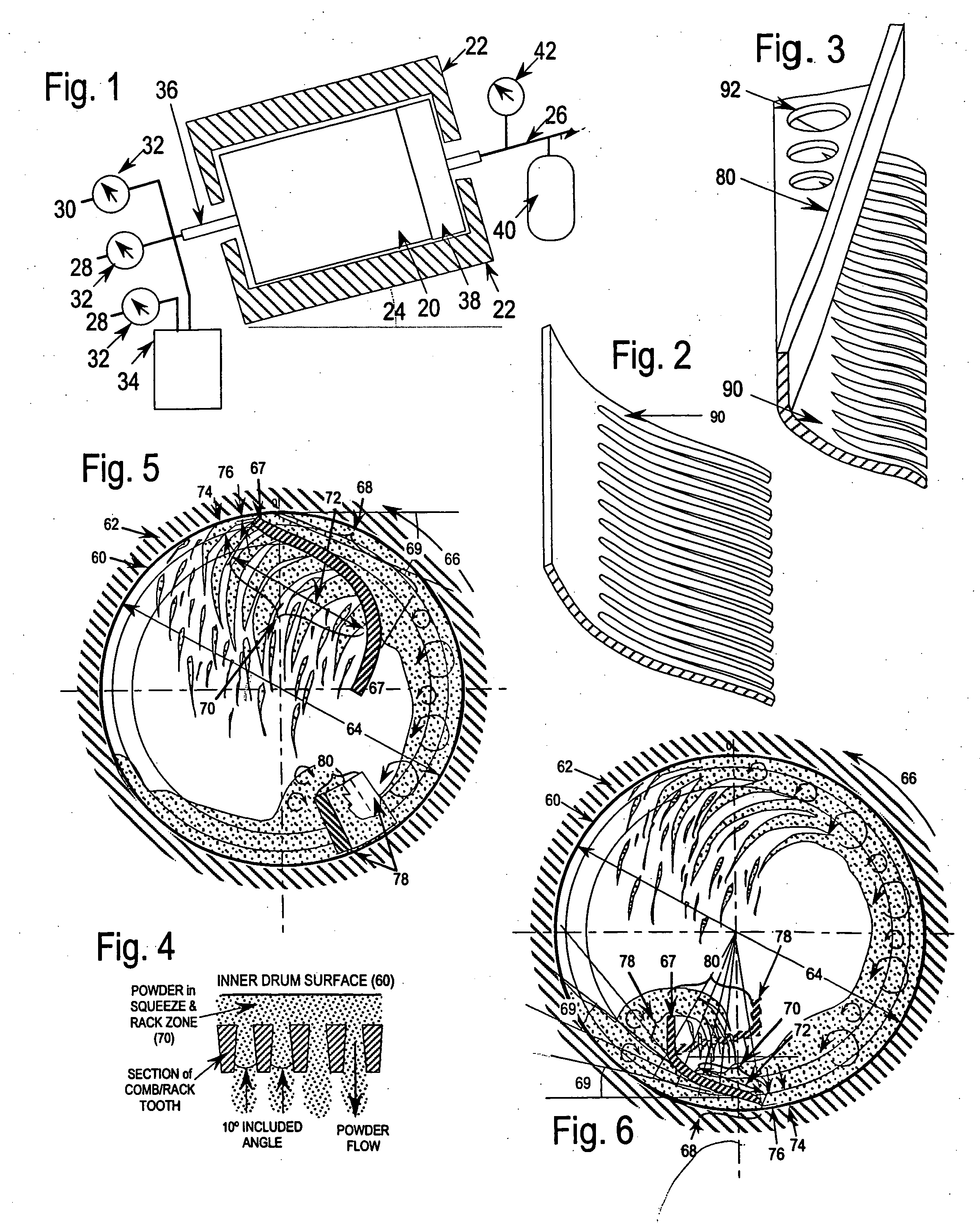
The patent describes an apparatus and method for treating particulate materials. The apparatus includes a container with a contacting surface and a rack with elongated apertures between comb-like teeth. The rack is set at an angle to the contacting surface to apply non-uniform compression to the particulate material. This non-uniform compression results in shear and tensile forces being applied to the particulate material, which causes it to flow through the elongated apertures. The method involves introducing the particulate material into the container and adjusting the relative motion between the contacting member and the interior surface of the container to create a reaction zone within the container. The non-uniform compression is sufficient to force the particulate material to flow through the elongated apertures, resulting in shear and tensile forces being applied to the particulate material. The method can be used to mix, blend, fluidize, deagglomerate, and coat particulate materials. The apparatus and method provide a way to effectively treat particulate materials and create coated particles with improved properties.

Problems solved by technology

The non-uniform compression is sufficient to force the particulate material to flow through the elongated apertures resulting in shear and tensile forces being applied to the particulate material.
While not wishing to be limited, it is believed that the non-uniform compression provides a flow gradient to the particulate material flowing through the elongated apertures.
The non-uniform compression is sufficient to force the particulate material to flow through the elongated apertures resulting in shear and tensile forces being applied to the particulate material.

Method used


Image

  • Apparatus and method of treating fine powders
  • Apparatus and method of treating fine powders

Examples


example

[0095] The apparatus hereinabove described was employed to effect CVD coating of W2C on TiN powder to create TCHP. The reactor was tilted on its rotational axis at 15 degrees and the combined rack and guide was operated with a 20° helix angle and with the comb fixed at a squeeze angle of generally between about 13 and about 60 degrees. The final angle used was approximately 60 degrees. A suitable amount of TiN core powder was introduced into the chamber of the graphite reactor. The system was purged, hydrogen flow initiated, and the internal pressure adjusted to 11.25 Torr. Power was then supplied to the electric furnace to bring the drum of the reactor, rotating at 90 revolutions per minute, to a temperature of about 550° C., for about one hour. The flow meters for the WF6 supply and the cumene bubbler were then opened to provide a molar ratio of the reactants suitable for the deposit of W2C on the TiN substrate powder. The bubbler operated at 20° C., and hydrogen gas was used as t...


PUM

PropertyMeasurementUnit
rake angleaaaaaaaaaa
sizeaaaaaaaaaa
diameteraaaaaaaaaa

Abstract

The present invention relates to an apparatus and method for economic treatment of Geldhart class C or larger substrate powders of single or plural metal, ceramic, or polymeric materials. In particular, the present invention is directed to coating such powder via a fluidized CVD or PVD, electroless, electrochemical, or solution chemistry plating process, and provides processes and apparatus for accomplishing same. It is particularly suited to coating with single or plural layers of metal, ceramic, binder, sintering aid, or polymer onto such materials without agglomeration. The coated particles and products made therefrom exhibit novel physical properties that are not limited by classical chemical and thermodynamic constraints.

Description

CROSS REFERENCE TO RELATED APPLICATION [0001] This application is a continuation-in-part of U.S. application Ser. No. 10 / 079,504, filed on Feb. 22, 2002, which is a divisional application of U.S. application Ser. No. 09 / 423,229, filed on Feb. 29, 2000, now U.S. Pat. No. 6,372,346, which is the national stage filing of PCT / US98 / 09767, filed May 13, 1998, which claims priority under 35 U.S.C. §119(e) to U.S. provisional application No. 60 / 046,885 filed May 13, 1997, the subject matter of which is incorporated by reference herein.BACKGROUND OF THE INVENTION [0002] 1. Field of the Invention [0003] The invention relates to the treatment, and particularly the encapsulation and deagglomeration of particles previously difficult to coat in a fluidized bed, for example, because of the size and / or density of the particles. Such particles generally comprise metal, binder, ceramic, refractory, or polymer with a coating or coatings of metal, binder, ceramic, sintering aid, or polymer. [0004] 2. B...

Claims


Application Information

Patent Timeline
Patent Type & Authority Applications(United States)
IPC IPC(8): B05D7/00A23G3/20A23G3/26B22F1/08B22F1/17B22F1/18C09K3/14C22C29/00
CPCB22F1/02Y10T428/13B22F2005/001B22F2998/00B23B27/148C04B35/62831C04B41/009C04B41/4584C04B41/87C04B2235/3886C09K3/1445C22C29/00C23C16/32C23C16/4417C23C24/06B22F1/025B22F2207/07C04B41/4531C04B41/5057C04B35/58B22F1/17B22F1/18B22F1/08
Inventor TOTH, RICHARD E.
Owner ETERNALOY HLDG GMBH
Learn More