Control valve for a fuel injector that contains a pressure intensifier

a technology of pressure intensifier and control valve, which is applied in the direction of fuel injection apparatus, machine/engine, feed system, etc., can solve the problems of relatively high production cost, and limited attainable pressure level of reservoir injection system in current use, so as to reduce leakage and production. the effect of facilitating production and reducing the guide portion of the servo piston

Inactive Publication Date: 2006-09-07
ROBERT BOSCH GMBH
View PDF10 Cites 35 Cited by
  • Summary
  • Abstract
  • Description
  • Claims
  • Application Information

AI Technical Summary

Benefits of technology

[0007] If a servo valve piston is embodied with only one guide portion, which is subjected to system pressure (rail pressure) in the state of repose of the fuel injector, the leakage can be reduced considerably. This one guide portion has a smaller sealing diameter, since in this portion, no valve pockets for connecting control bores have to be provided. Production can furthermore be facilitated because the total length of the guide portion of the servo piston is shorter.
[0008] As an alternative to embodying the control valve as a 3/2-way slide-slide valve with only one guide portion, which in the state of repose of the fuel injector is subjected to rail pressure, an additional valve seat can be employed to further reduce leakage losses. This additional valve seat may be embodied as a flat seat, and it is structurally simple to provide inside a two-part valve housing

Problems solved by technology

For the sake of durability, the attainable pressure level in reservoir injection systems in current use is presently limited to about 1600 bar.
A disadvantage of this version is the relatively high production cost for controlling such a fuel injection system, with two valves and two independently activatable actuators.
However, this means relatively high production costs.
This in turn means that an

Method used


Image

  • Control valve for a fuel injector that contains a pressure intensifier
  • Control valve for a fuel injector that contains a pressure intensifier
  • Control valve for a fuel injector that contains a pressure intensifier

Examples


Embodiment Construction

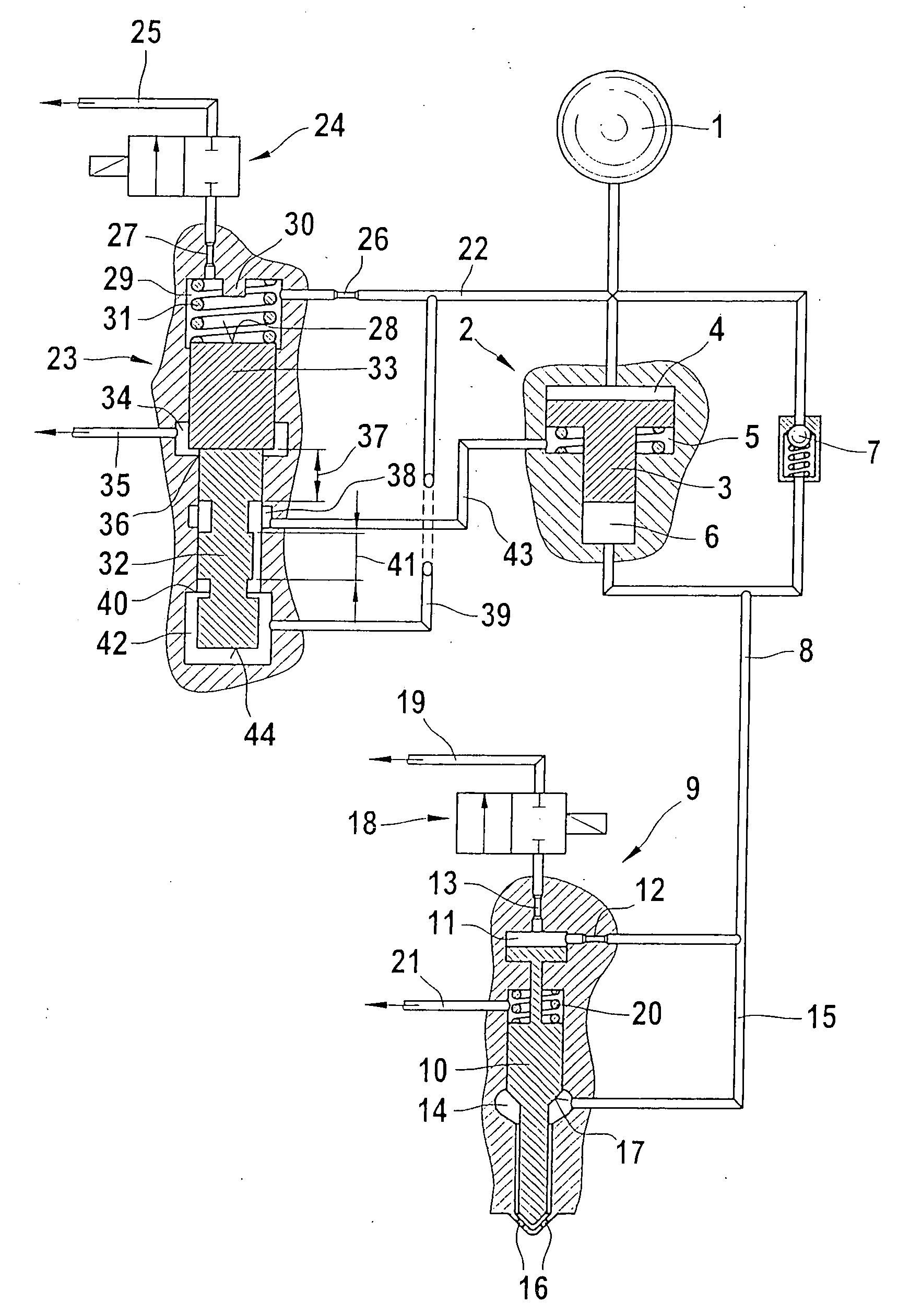
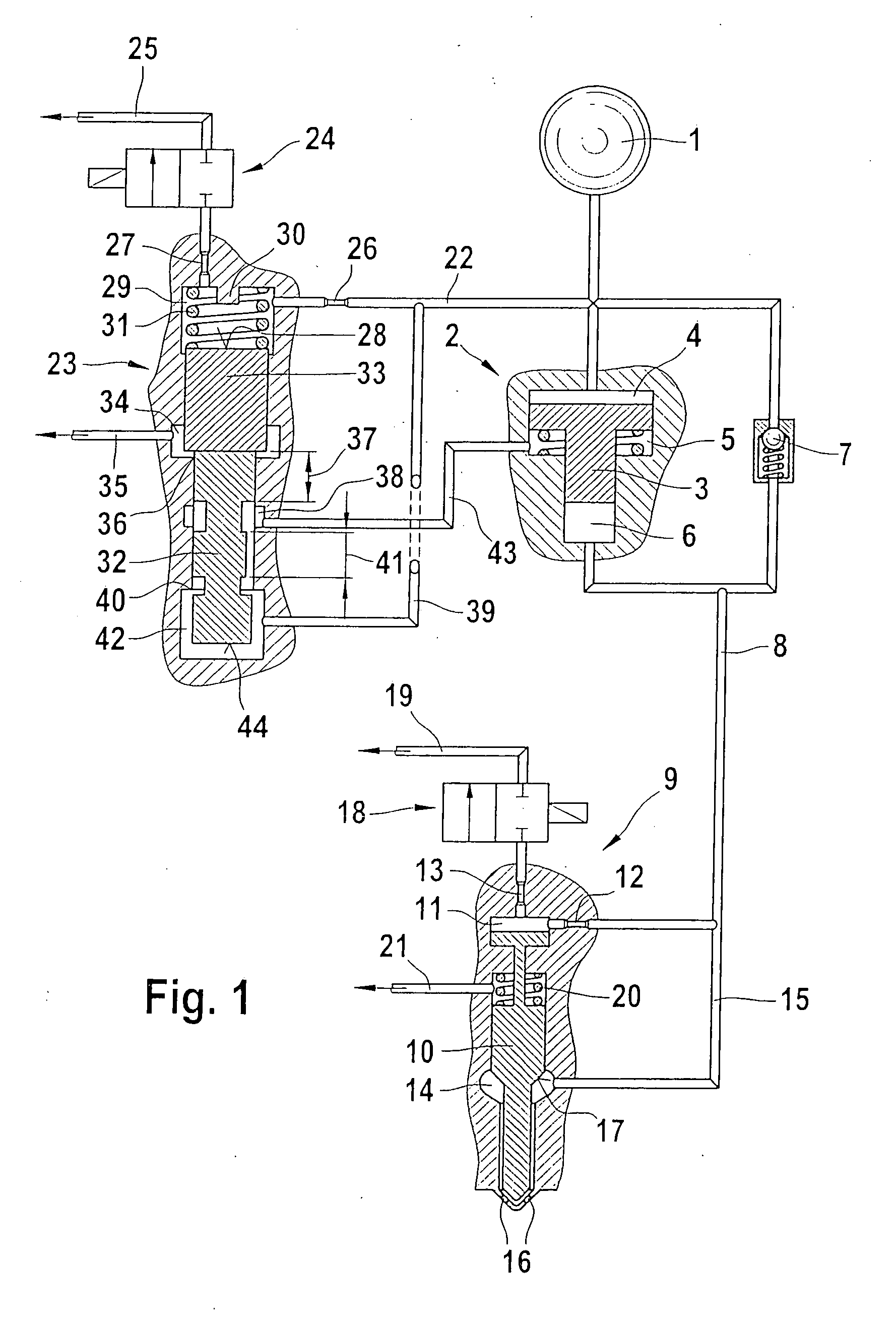
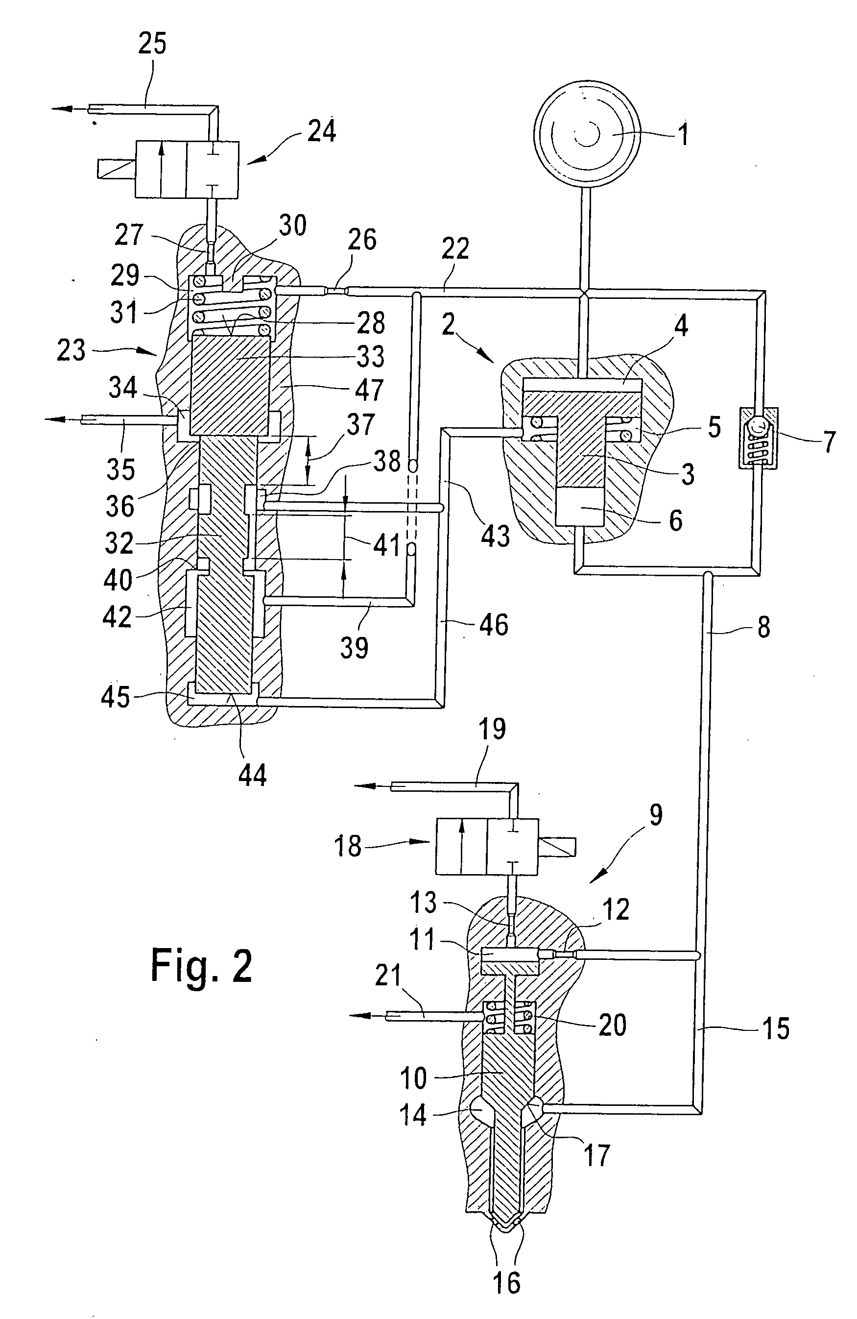
[0018]FIG. 1 shows a servo valve, embodied as a slide valve, for triggering a pressure booster of a fuel injector.

[0019] Via a high-pressure source 1, which may be either a high-pressure collection chamber (common rail) or a high-pressure fuel pump, a pressure booster 2 is acted upon by fuel that is at high pressure. The pressure booster 2 includes both a work chamber 4 and a differential pressure chamber 5, which are separated from one another by a booster piston 3. The pressure booster 2 furthermore includes a compression chamber 6. From it, a high-pressure line 8 branches off, and a check valve 7 is received in the refilling branch of the pressure booster 2.

[0020] Via the high-pressure line 8, a fuel injector 9 is acted upon by boosted pressure—in accordance with the boosting ratio of the pressure booster 2. The high-pressure line 8 merges with a nozzle chamber inlet 15, by way of which a nozzle chamber 14 is acted upon by fuel. From the high-pressure line 8, a first inlet thro...


PUM


Abstract

A servo valve for actuating a pressure booster of a fuel injector, the pressure booster having a work chamber separated by a booster piston from a differential pressure chamber and the pressure change in the differential pressure chamber of the pressure booster is effected via the servo valve, via switching valve. The control chamber of the servo valve can both be made to communicate with a high-pressure source and pressure-relieved into a low-pressure-side return, and for generating a fast closing motion at the valve piston, a pressure shoulder acting in the closing direction of the valve piston is embodied between the control chamber and the hydraulic chamber, and control edges without a common opening phase are embodied on the valve piston.

Description

FIELD OF THE INVENTION [0001] For supplying combustion chambers of self-igniting internal combustion engines with fuel, both pressure- controlled and stroke-controlled injection systems may be employed. As fuel injection systems, not only unit fuel injectors and pump-line-nozzle units but also reservoir injection systems are used. Advantageously, reservoir injection systems (common rails) make it possible to adapt the injection pressure to the load and rpm of the engine. To attain high specific performance and to reduce emissions from the engine, an injection pressure that is as high as possible is generally required. BACKGROUND OF THE INVENTION [0002] For the sake of durability, the attainable pressure level in reservoir injection systems in current use is presently limited to about 1600 bar. To further increase the pressure in reservoir injection systems, pressure boosters are employed with them. [0003] German Patent Disclosure DE 101 23 910.6 refers to a fuel injection system wit...

Claims


Application Information

Patent Timeline
IPC IPC(8): F02M57/02F02M47/02F02M59/10F02M63/00
CPCF02M47/027F02M57/025F02M57/026F02M59/105F02M63/0005F02M63/0007
Inventor MAGEL, HANS-CHRISTOPH
Owner ROBERT BOSCH GMBH
Why Eureka
Try Eureka