Solid-state image pickup device, electronic apparatus using such solid-state image pickup device and method of manufacturing solid-state image pickup device

a solid-state image and pickup device technology, applied in the direction of radio frequency controlled devices, instruments, transportation and packaging, etc., can solve the problems of reducing the speed at which a signal is transmitted from the sensor chip to the signal processing device, the increase of the chip area, and the formation of electrodes, so as to improve the sensitivity of the solid-state image pickup device and the camera, the effect of reducing the saturation electric charge amount and sensitivity

Active Publication Date: 2006-09-07
SONY CORP
View PDF0 Cites 172 Cited by
  • Summary
  • Abstract
  • Description
  • Claims
  • Application Information

AI Technical Summary

Benefits of technology

[0048] In view of the aforesaid aspect, the present invention intends to provide a solid-state image pickup device in which the pixel size can be made very small without lowering a saturation electric charge amount (Qs) and sensitivity.
[0050] Furthermore, the present invention intends to provide a process of simply and easily manufacturing a back-illuminated type CMOS solid-state image pickup device having an arrangement in which an electrode is led out from the surface of the opposite side of the light illuminated surface.
[0076] According to the solid-state image pickup device and the camera of the present invention, the solid-state image pickup device and the camera are composed of the back-illuminated type solid-state image pickup device, wherein electric charges generated from the photo-electric conversion region portion formed under at least a part of the read circuit are collected to the electric charge accumulation region of the photo-electric conversion element by the electric field formed within the photo-electric conversion element, whereby a saturation electric charge amount can be increased. On the other hand, since the portion provided under the read circuit also is formed as the photo-electric conversion element, the incident light area in which light is introduced from the other surface of the substrate can be increased and hence sensitivity of the solid-state image pickup device and the camera can be improved. Accordingly, it becomes possible to make the pixel size become very small in accordance with increase of integration degree of pixel without lowering a saturation electric charge amount and sensitivity.
[0077] The potential distribution of which potential is increased from the photo-electric conversion region portion to the electric charge accumulation region is formed between the above-described photo-electric conversion region portion and electric charge accumulation region within the photo-electric conversion element, whereby electric charges can be moved from the photo-electric conversion region portion and accumulated in the electric charge accumulation region efficiently.
[0078] The potential distribution of which potential is increased toward the other plane of the substrate or one plane in the substrate depth direction of the photo-electric conversion element, whereby electric charges generated within the photo-electric conversion element can be efficiently moved to and accumulated in the electric charge accumulation region which exists on one plane.
[0079] Also, according to the method of manufacturing a solid-state image pickup device and a camera of the present invention, since the semiconductor substrate is decreased in thickness after the supporting substrate was bonded to the semiconductor substrate to maintain sufficient strength and the supporting substrate is decreased in thickness to form the penetrating wirings, it is possible to simply and easily manufacture the back-illuminated type CMOS solid-state image pickup device and the camera having the arrangement in which the electrode is led out from the surface of the opposite side of the light illuminated surface.

Problems solved by technology

In the back-illuminated type CMOS solid-state image pickup device (image sensor) having the above-described arrangement, since the pad electrode has to be large enough to be connected by wiring bonding, the chip area is increased unavoidably.
Also, since the number of electrodes that can be formed within the chip is limited and high-resistance wiring bonding is used, speed at which a signal is transmitted from the sensor chip to the signal processing device is lowered.

Method used


Image

  • Solid-state image pickup device, electronic apparatus using such solid-state image pickup device and method of manufacturing solid-state image pickup device
  • Solid-state image pickup device, electronic apparatus using such solid-state image pickup device and method of manufacturing solid-state image pickup device
  • Solid-state image pickup device, electronic apparatus using such solid-state image pickup device and method of manufacturing solid-state image pickup device

Examples


first embodiment

[0092] the present invention will hereinafter be described with reference to the drawings.

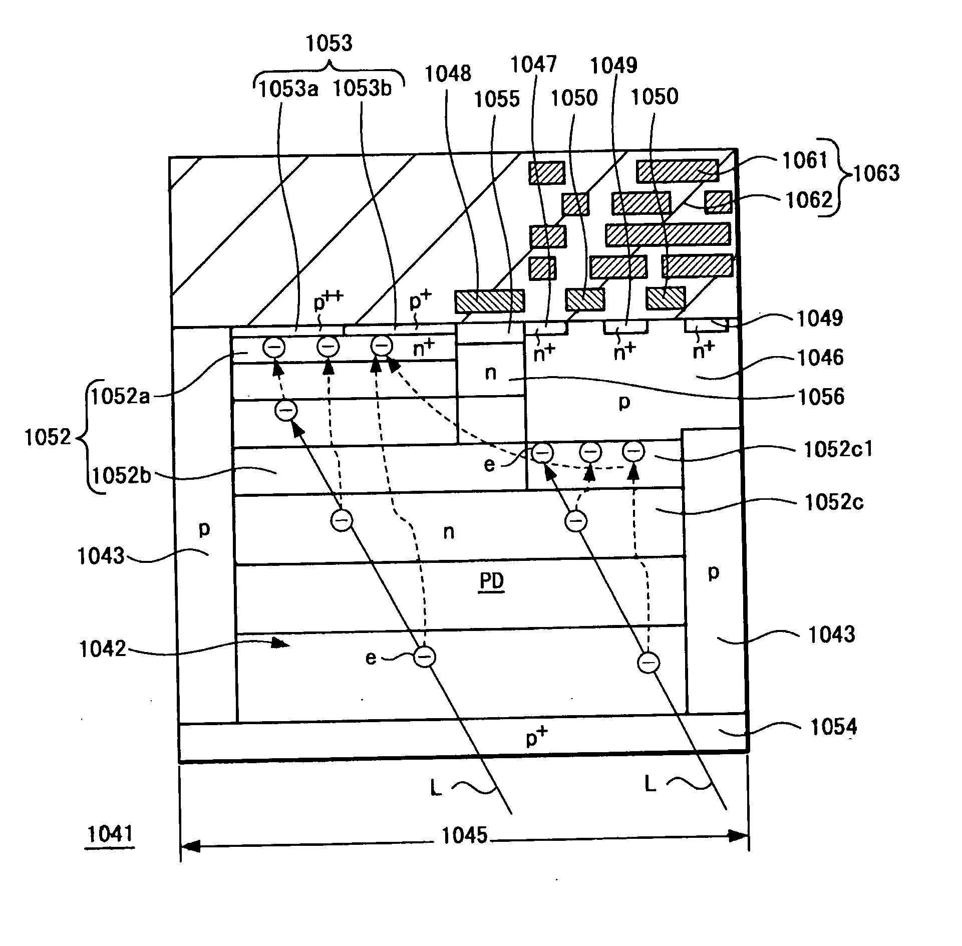
[0093]FIG. 5 is a schematic diagram showing an arrangement of a back-illuminated type CMOS solid-state image pickup device according to the present invention.

[0094] As shown in FIG. 5, a back-illuminated type CMOS solid-state image pickup device 1040 includes a first conductivity type, for example, an n type silicon semiconductor substrate 1042 on which a pixel separation region formed of a second conductivity type, for example, a p type semiconductor region to divide respective pixels is formed. On each divided area, there is formed a unit pixel 1045 composed of a photodiode PD and a plurality of MOS transistors, for example, four MOS transistors of an electric charge read transistor Tr1, a reset transistor, an amplifier transistor and a vertical selection transistor (all of which will be generally referred to a “Tr2”). A large number of unit pixels 1045 are arranged in an XY matrix fashion (...

second embodiment

[0115] the present invention will be described.

[0116]FIG. 7 is a schematic cross-sectional view showing an arrangement of an electronic apparatus in which the back-illuminated type CMOS solid-state image pickup device according to the first embodiment of the present invention is mounted.

[0117] As shown in FIG. 7, a sensor chip 1a, which is a back-illuminated type CMOS solid-state image pickup device with an image pickup pixel unit provided thereon, and a signal processing chip 2 with a peripheral circuit unit such as a signal processing circuit provided thereon, are mounted on an interposer (intermediate substrate) 3, for example.

[0118] The sensor chip 1a has an interlayer insulator 20 formed on a supporting substrate 30 and a buried wiring layer 21 buried therein. A semiconductor layer 12 is formed on the buried wiring layer 21 and a surface insulating layer 11 is formed on the surface of the semiconductor layer 12.

[0119] A photodiode 14 and an alignment mark 13 and the like are...

third embodiment

[0160] the present invention will be described below.

[0161]FIG. 11 is a schematic cross-sectional view showing an arrangement of an electronic apparatus in which the back-illuminated type CMOS solid-state image pickup device according to the embodiment of the present invention is mounted.

[0162] Similarly to the second embodiment, a sensor chip 1b, which is a back-illuminated type CMOS solid-state image pickup device with an image pickup pixel unit provided thereon, and the signal processing chip 2 with the peripheral circuit unit such as the signal processing circuit provided thereon are mounted on the interposer (intermediate substrate) 3, for example.

[0163] As shown in FIG. 11, the interlayer insulator 20 is formed on the supporting substrate 30 and the buried wiring layer 21 is buried in the inside of the interlayer insulator 20. The semiconductor layer 12 is formed on the upper layer of the buried wiring layer 21 and the surface insulating films (11, 19) are formed on the surf...


PUM


Abstract

A back-illuminated type solid-state image pickup device (1041) includes read circuits (Tr1, Tr2) formed on one surface of a semiconductor substrate (1042) to read a signal from a photo-electric conversion element (PD) formed on the semiconductor substrate (1042), in which electric charges (e) generated in a photo-electric conversion region (1052c1) formed under at least one portion of the read circuits (Tr1, Tr2) are collected to an electric charge accumulation region (1052a) formed on one surface side of the semiconductor substrate (1042) of the photo-electric conversion element (PD) by electric field formed within the photo-electric conversion element (PD). Thus, the solid-state image pickup device and the camera are able to make the size of pixel become very small without lowering a saturation electric charge amount (Qs) and sensitivity.

Description

CROSS REFERENCES TO RELATED APPLICATIONS [0001] The present invention contains subject matter related to Japanese Patent Applications JP 2005-062714 filed in the Japanese Patent Office on Mar. 7, 2005, JP 2005-163267 filed in the Japanese Patent Office on Jun. 2, 2005 and JP 2006-012106 filed in the Japanese Patent Office on Jan. 20, 2006, the entire contents of which being incorporated herein by reference. BACKGROUND OF THE INVENTION [0002] 1. Field of the Invention [0003] The present invention generally relates to a solid-state image pickup device and more particularly to a back-illuminated type CMOS (complementary metal-oxide semiconductor) solid-state image pickup device in which incident light is introduced from the back side of a substrate, an electronic apparatus using such solid-state image pickup device and a method of manufacturing such solid-state image pickup device. [0004] 2. Description of the Related Art [0005] A CMOS solid-state image pickup device is known as a soli...

Claims


Application Information

Patent Timeline
Patent Type & Authority Applications(United States)
IPC IPC(8): H01L27/00
CPCH01L27/14601H01L27/14634H01L27/14636H01L27/14643H01L27/1469H01L2924/3025H01L2224/48145H01L2224/48464H01L27/1464H01L2924/13091H01L2224/48091H01L2924/00014H01L2924/00H01L2224/13025H01L2224/16225H01L2224/05573H01L2224/056H01L2224/0554H01L27/14687H01L27/1463H01L27/14638H01L2924/00012H01L2224/05599H01L2224/0555H01L2224/0556B65G45/18B08B1/02B08B1/002B65G2201/045B65G2812/02128H01L31/1136H01L31/035272H01L2224/45147
Inventor IWABUCHI, SHINYOKOTA, KAZUHIDEYANAGITA, TAKESHIMARUYAMA, YASUSHI
Owner SONY CORP
Why Eureka
Try Eureka