Aspirator having a cushioned and aspiration controlling tip

a technology of aspirator and tip, which is applied in the field of tubular appliances, can solve the problems of affecting the quality of life of the patient, so as to reduce the effect of reducing the potential for tissue damag

Active Publication Date: 2006-09-07
MAHLMANN LEE A
View PDF15 Cites 32 Cited by
  • Summary
  • Abstract
  • Description
  • Claims
  • Application Information

AI Technical Summary

Benefits of technology

[0015] For high speed aspiration an alternative tip design is provided wherein a soft tip is provided with a reduced diameter tubular connector which is received and secured within the inner flow passage of a polymer tube which is intended to be grasped by a practitioner for aspirator manimulation. The head of the aspirator tip defines a shoulder that engages the circular end to the tube and thus establishes the desired position of the aspirator tip relative to an end of the tubular aspirator member. The head portion of the aspirator tip defines a smoo...

Problems solved by technology

The tissue inside the human mouth and lip area around the mouth and also boney areas within the oral cavity are very sensitive and can be easily damaged when aspiration occurs and when an aspirator comes into contact with such tissues.
The problem with most tubular saliva ejectors or aspirators is that they are typically composed of a hard, non-forgiving plastic or metal and define a large diameter end opening through which aspiration occurs.
When positioned under the tongue or in the labial vestibule of a patient's oral cavity, the saliva ejector aspirates saliva, blood, and unfortunately also aspirates the soft, flaccid, easily damaged oral tissues that are present.
The suction of aspiration can cause the tissue to be pulled into the aspirator opening, blocking the opening and subjecting the soft tissue to significant vacuum induced force.
When the aspirator tube is removed from the mouth as suction is being applied, pulling it away from the patient's tissu...

Method used


Image

  • Aspirator having a cushioned and aspiration controlling tip
  • Aspirator having a cushioned and aspiration controlling tip
  • Aspirator having a cushioned and aspiration controlling tip

Examples


Embodiment Construction

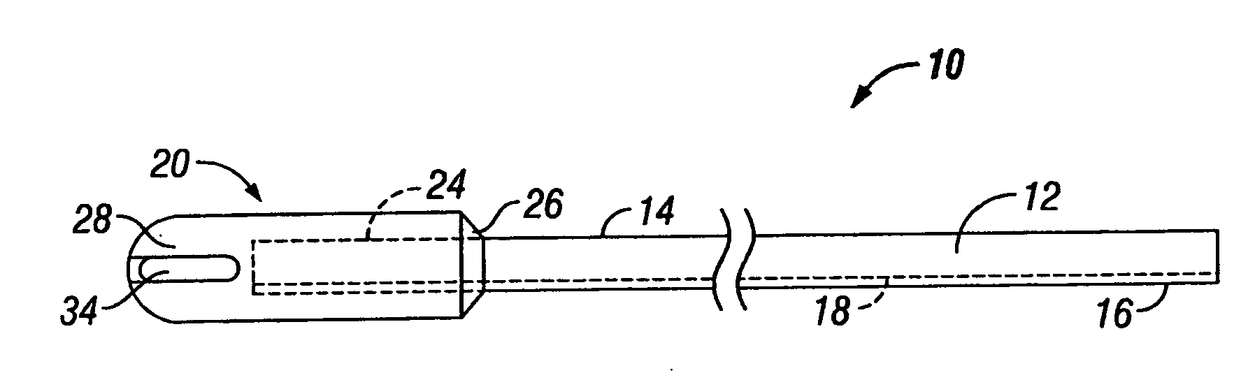
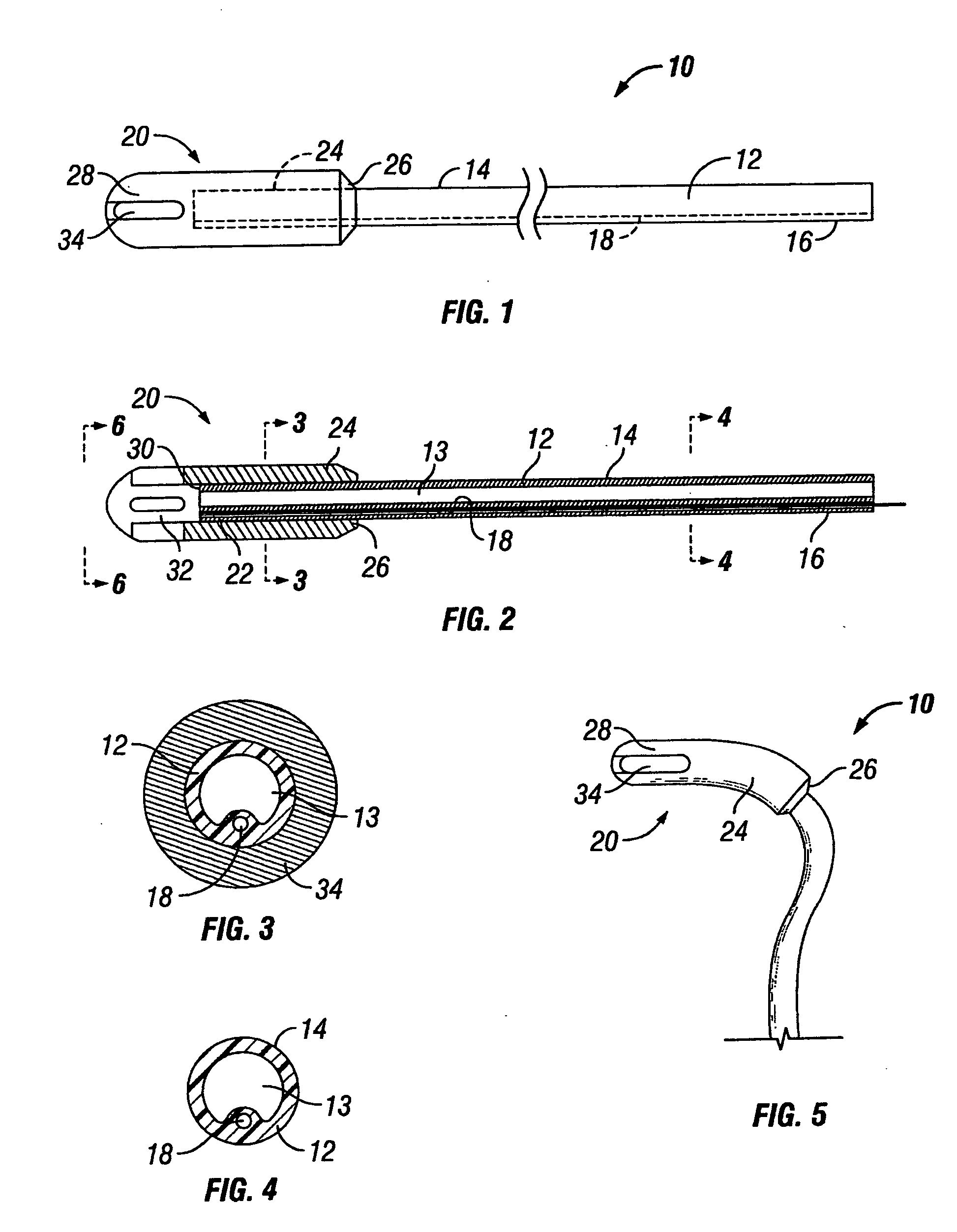
[0041] Referring now to the drawings and first to FIGS. 1-5, a disposable formable cushioned aspirator representing the preferred embodiment of the present invention is shown generally at 10. The formable-cushioned aspirator 10 consists of an elongated hollow flexible tube 12 preferably composed of a suitable polymer or rubber and defining a generally cylindrical external surface 14 extending substantially the entire length thereof. The elongate flexible hollow tubular element 12 has a central flow passage 13 and defines a connector end section 16 to which is assembled a suction tube connector 17 that enables attachment of the formable cushioned aspirator 10 to the usual flexible tube of a central vacuum pump or vacuum system (not shown). The flexible tubing and the suction tube connector 17 may be of conventional nature, but preferably it is fixed to the connector end section 16 of the flexible hollow tubular element 12. This feature permits an aspirator to be releasably assembled ...


PUM


Abstract

A disposable cushioned aspirator which forms part of a dental or medical aspirating system. The disposable cushioned aspirator appliance described herein is intended principally to be used in dental and medical procedures where body fluids and rinse water is evacuated from the site of a procedure. An elongate tubular element has a connection end and a patient end. The patient end is exteriorly lined with a layer of soft cushioning material such as a soft thermoplastic elastomers, styrene based polymers, rubber or a porous polymer foam material to define an aspirator tip that protects the soft tissues in and around the mouth of a patient. The soft aspirator tip has external longitudinal pressure relief channels and recessed aspiration openings within the channels for control of aspiration characteristics. The aspirator tube is capable of being manually bent to a desired configuration and has an embedded structural member such as wire extending along its length and being pliable to permit bending and yet of sufficient structural integrity to maintain the aspirator in the desired configuration during use.

Description

RELATED PATENT [0001] The present invention is related to the subject matter of U.S. Pat. No. 6,068,477, entitled “Foam Cushioned Aspirator”, filed on Jul. 6, 1999 by Lee A. Mahlmann and issued on May 30, 2000. RELATED PROVISIONAL APPLICATION [0002] Applicant hereby claims the benefit of U.S. Provisional Patent Application No. 60 / 514,477, filed on Oct. 23, 2003 by Lee A. Mahlmann and entitled “Aspirator Having Cushioned Section”. RELATED APPLICATION [0003] This is a Continuation-in-Part application based on pending application Ser. No. 11 / 323,876 which was filed by Lee A. Mahlmann on Dec. 31, 2005 and entitled Aspirator Having Cushioned and Aspiration controlling tip and application Ser. No. 10 / 909,725 which was filed on Aug. 2, 2004 by Lee A. Mahlmann and entitled “Aspirator Having Cushioned Tip”.BACKGROUND OF THE INVENTION [0004] 1. Field of the Invention [0005] This invention relates generally to tubular appliances such as tubular aspirators, intubation members and the like for u...

Claims


Application Information

Patent Timeline
IPC IPC(8): A61C17/06
CPCA61C17/043A61C17/092A61C17/096A61C17/08
Inventor MAHLMANN, LEE A.
Owner MAHLMANN LEE A
Why Eureka
Try Eureka