MIMO receiver, MIMO reception method and wireless communication system

a receiver and receiver technology, applied in the field of mimo receiver and mimo reception method, can solve the problems of mmse weight precision decline, conventional mimo receiver, interference of desired transmit antenna signals with ds-cdma signals, etc., and achieve excellent characteristics

Active Publication Date: 2006-09-07
NEC CORP
View PDF3 Cites 25 Cited by
  • Summary
  • Abstract
  • Description
  • Claims
  • Application Information

AI Technical Summary

Benefits of technology

[0034] As is described above, in accordance with the present invention, when each transmit antenna uses a different chip power ratio in MIMO filter reception, the MIMO receiver corrects pilot power so that the chip power ratio of each transmit antenna is equal to that of the reference transmit antenna and calculates filter weights to perform accurate MMSE control, thereby achieving excellent characteristics.

Problems solved by technology

When the MIMO multiplexing is applied to DS-CDMA (Direct Sequence-Code Division Multiple Access) signals, in addition to interference from other transmit antennas, the multipath of desired transmit antenna signals interferes with the DS-CDMA signals.
The conventional MIMO receiver, however, has the following problem.
Consequently, when the transmit antennas use different chip power ratios (perform adaptive modulation, etc.), respectively, the MMSE weight precision decreases, and the characteristics deteriorate.

Method used


Image

  • MIMO receiver, MIMO reception method and wireless communication system
  • MIMO receiver, MIMO reception method and wireless communication system
  • MIMO receiver, MIMO reception method and wireless communication system

Examples


Embodiment Construction

[0042] Referring now to the drawings, a description of a preferred embodiment of the present invention will be given in detail.

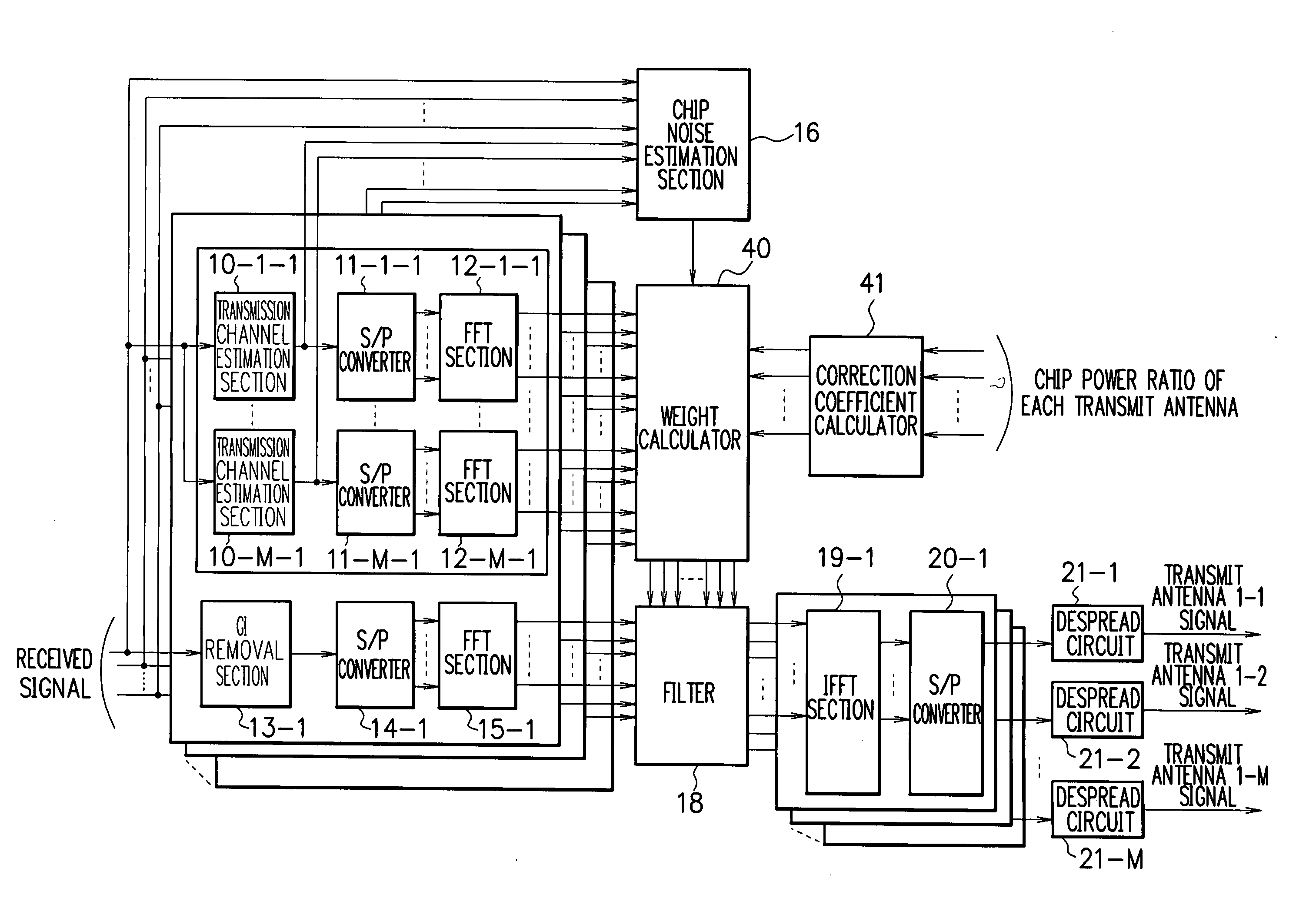
[0043]FIG. 4 is a diagram showing the construction of a MIMO receiver according to an embodiment of the present invention. Incidentally, in FIG. 4, like portions are designated by like reference numerals as in FIG. 2. Referring to FIG. 4, a description will be given of the MIMO receiver with M (M: an integer not less than 1) transmit antennas and N (N: an integer not less than 1) receive antennas.

[0044] As can be seen in FIG. 4, the MIMO receiver comprises transmission channel estimation sections 10-1-1 to 10-M-N, S / P (Serial to Parallel) converters 11-1-1 to 11-M-N and 14-1 to 14-N, FFT (Fast Fourier Transform) sections 12-1-1 to 12-M-N and 15-1 to 15-N, GI (Guard Interval) removal sections 13-1 to13-N, a chip noise estimation section 16, a filter 18, IFFT (Inverse Fast Fourier Transform) sections 19-1 to 19-M, P / S (Parallel to Serial) converters 20-1 to ...


PUM


Abstract

A MIMO receiver, a MIMO reception method and a wireless communication system capable of accurate MMSE control even when each transmit antenna uses a different chip power ratio in MIMO filter reception. A correction coefficient calculator receives as input the chip power ratio of each transmit antenna, and estimates such pilot power that renders the chip power ratio of each transmit antenna equal to that of a reference transmit antenna. Thereby, the correction coefficient calculator calculates a correction coefficient βm to correct the actual pilot power of each transmit antenna. A weight calculator receives as input transmission channel impulse responses transferred into frequency domain by FFT sections, chip noise power estimated by a chip noise estimation section, and the correction coefficient βm obtained by the correction coefficient calculator. The weight calculator calculates filter weights according to the minimum mean square error (MMSE) criterion.

Description

FIELD OF THE INVENTION [0001] The present invention relates to a MIMO receiver, a MIMO reception method and a wireless communication system, and more particularly, to a MIMO receiver, a MIMO reception method and a wireless communication system for demodulating signals according to the minimum mean square error (MMSE) criterion with a plurality of receive antennas. BACKGROUND OF THE INVENTION [0002] In a wireless communication system for the next-generation mobile communications, it is important to achieve high-speed data transmission. As a technology to realize high-speed data transmission, the MIMO (Multiple Input Multiple Output) multiplexing system attracts attention. According to the MIMO multiplexing system, signals are transmitted at the same frequency and time through a plurality of transmit antennas, and the signals are demodulated (separated) through a plurality of receive antennas. [0003]FIG. 1 is a diagram showing a MIMO transmitter / receiver having M (M: an integer not le...

Claims


Application Information

Patent Timeline
Patent Type & Authority Applications(United States)
IPC IPC(8): H04B1/10H04J99/00
CPCH04B1/7097H04B7/04H04B7/0684H04W52/16H04W52/42
Inventor KIMATA, MASAYUKIYOSHIDA, SHOUSEI
Owner NEC CORP
Why Eureka
Try Eureka