Optical scanner and image forming apparatus

a technology of optical scanner and image forming apparatus, which is applied in the direction of digitally marking record carriers, visual presentation using printers, instruments, etc., can solve the problems of reducing the cost and dimensions of the overall apparatus, difficult to let the light flux from the light source, and the cost of the polygon mirror section occupies a considerable portion of the cos

Active Publication Date: 2006-09-14
RICOH KK
View PDF4 Cites 32 Cited by
  • Summary
  • Abstract
  • Description
  • Claims
  • Application Information

AI Technical Summary

Benefits of technology

[0023] It is an object of the present invention to a...

Problems solved by technology

In general, the cost of the polygon mirror section occupies a considerable portion in the cost of optical elements constituting the optical scanner, and hence employing a large polygon mirror constitutes a bottleneck against a reduction in cost and dimensions of the overall apparatus.
There are issues when employing a polygon mirror as the light deflector in the oblique incidence optical system.
It is difficult to let the light flux from the light source enter the rotation axis of the polygon mirror, by an ordinary incidence system.
Moreover, a larger polygon mirror requires larger energy for high-speed rotation thereof, and since wind noise due to the high-speed rotation naturally becomes larger, a larger scale sound shielding means is required.
The oblique incidence system has, however, a drawback that a larger scanning line curvature is incurred.
The amount of curvature in the scanning line differs depending on the oblique incidence angle in the sub-scanning direction with respect to the deflecting reflection surface of each light beam, and such a difference is visualized upon developing the latent image drawn by each light beam on the photoconductor with a toner of the corresponding color, resulting in color deviation when the toner images are stacked.
Moreover, because of the oblique incidence the light flux is twisted when entering the scanning lens, which increases the wavefront aberration, thereby significantly degrading the optical performance especially at peripheral field height and thus increasing the beam spot diameter.
This obviously inhibits achieving a higher image quality.
Because of such a configuration, the oblique incidence angle to the deflecting reflection surface is increased in order to avoid interference with the scanning lens, which leads to an increase in the scanning line curvature ...

Method used


Image

  • Optical scanner and image forming apparatus
  • Optical scanner and image forming apparatus
  • Optical scanner and image forming apparatus

Examples


numerical example 1

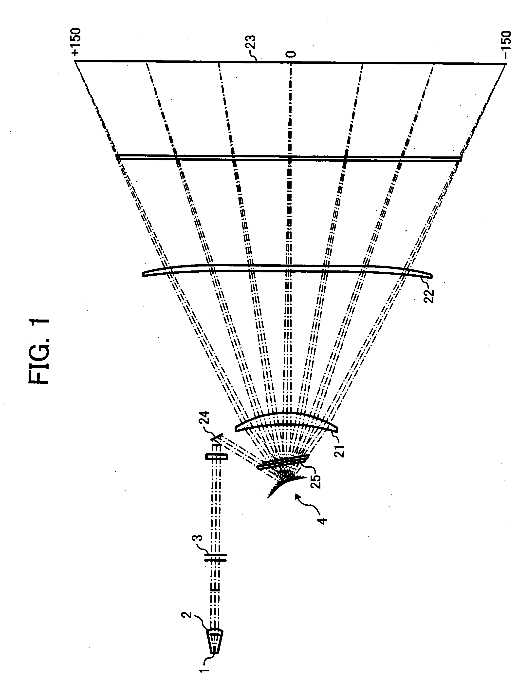
[0107] Hereinafter, examples of the optical scanner according to the present invention with specific numerical values will be cited. The semiconductor laser employed as the light source has an emission wavelength of 655 nm, and the divergent flux thereby emitted is converted into a “substantially parallel flux” by a coupling lens having a focal length of 15 millimeter, thus to form a “lengthy line image in the main scanning direction” on the position of the deflecting reflection surface of the polygon mirror surface, via a cylindrical lens having a focal length of 70 millimeter. The polygon mirror has six deflecting reflection surfaces, and an inscribed radius of 18 millimeter. Also, the rotating shaft and the deflecting reflection surfaces are formed in parallel, and the light beam is obliquely made incident upon the deflecting reflection surface at 2.4 degrees in the sub-scanning direction, while in the main scanning direction a light flux directed to the field height 0 is made in...


PUM


Abstract

An optical scanner includes a plurality of light source units, each light source unit outputting a corresponding light beam; a light deflector having a deflecting surface that deflects the light beams output from the light source units; and a scanning optical system that condenses each light beam deflected by the light deflector onto a corresponding scanning surfaces. The light beams output from the light source units make an angle in a sub-scanning direction with respect to a normal to the deflecting surface. At least one surface of the scanning optical system has not curvature in the sub-scanning direction, and is a special surface having different tilt decentration angles in the sub-scanning direction according to a position in the main scanning direction.

Description

CROSS-REFERENCE TO RELATED APPLICATIONS [0001] The present document incorporates by reference the entire contents of Japanese priority document, 2005-069323 filed in Japan on Mar. 11, 2005. BACKGROUND OF THE INVENTION [0002] 1. Field of the Invention [0003] The present invention relates to an optical scanner that can be used in an image forming apparatus such as a digital copier, a laser printer, a laser facsimile and so forth, and to an image forming apparatus that includes an optical scanner. [0004] 2. Description of the Related Art [0005] An optical scanner is used in laser printers or the like to scan a scanning surface and obtain image data of the scanning surface. A typical optical scanner includes a light deflector that receives a light beam from a light source and deflects the light beam, and a scanning / imaging optical system such as a fθ lens that condenses the deflected light beam to create a beam spot on a scanning surface and scan the scanning surface with the beam spot....

Claims


Application Information

Patent Timeline
IPC IPC(8): G06K15/12
CPCB41J2/473G02B26/123
Inventor MIYATAKE, NAOKI
Owner RICOH KK
Why Eureka
Try Eureka