Optical modulation method for a liquid crystal layer and liquid crystal device using the method
a liquid crystal layer and optical modulation technology, applied in static indicating devices, non-linear optics, instruments, etc., can solve the problems of a great deal of time and effort to find a new liquid crystal material, and its reliability is in doubt, and achieve excellent performance in practical use.
- Summary
- Abstract
- Description
- Claims
- Application Information
AI Technical Summary
Benefits of technology
Problems solved by technology
Method used
Image
Examples
first embodiment
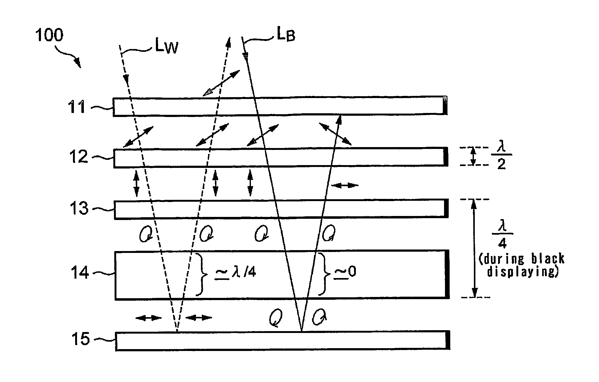
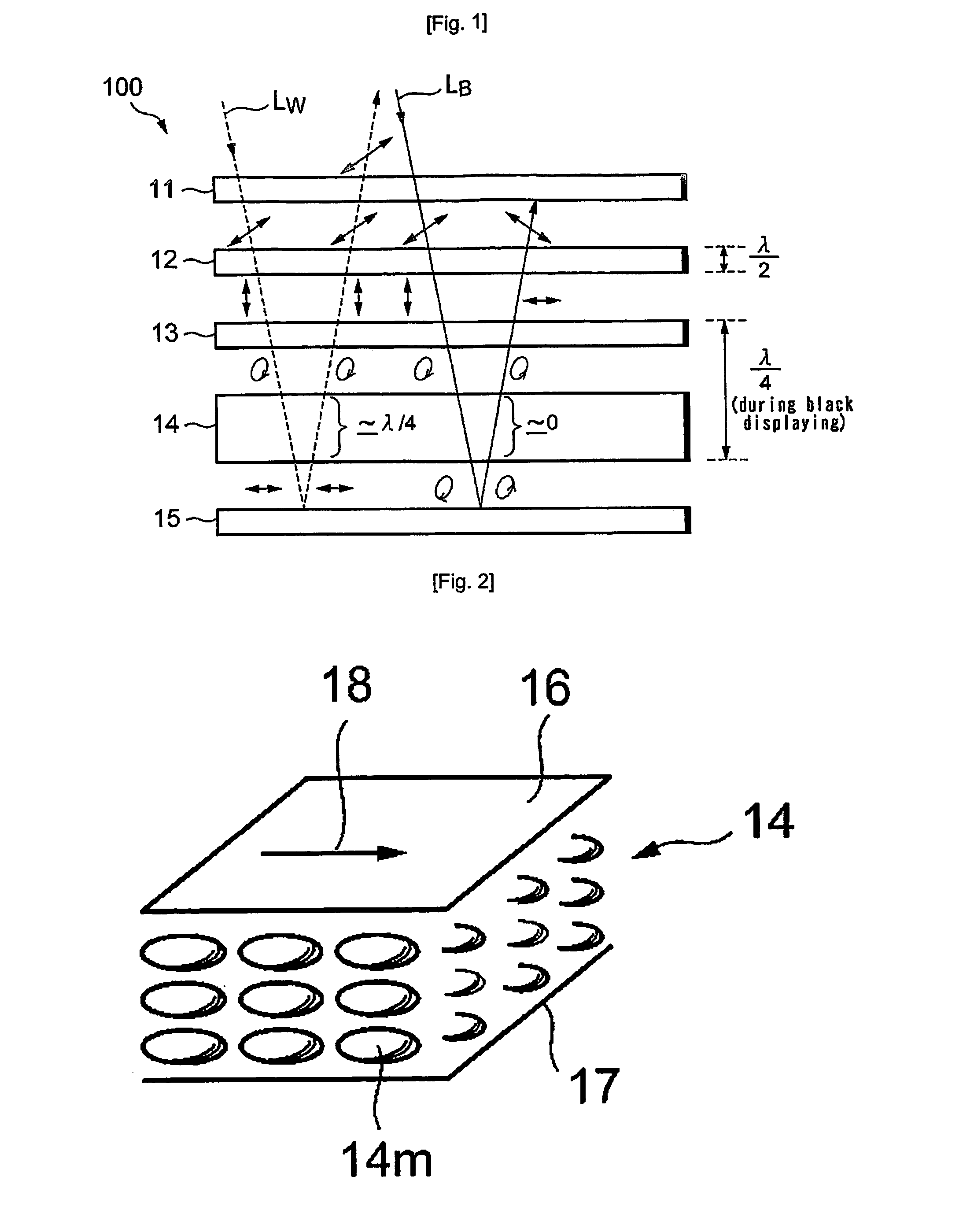
[0030]FIG. 1 schematically shows a sectional construction of a liquid crystal display device according to one embodiment of the invention.
[0031] A liquid crystal display device 100 is a reflective type liquid crystal display device, and has an arrangement of a linearly polarizing plate 11, a first retardation film 12 that is a half-wave plate, a second retardation film 13 that is a quarter-wave plate, a liquid crystal layer 14 which is sandwiched by a pair of electrodes (not shown) that apply a voltage corresponding to pixel information to be displayed, and an optical reflective layer 15, in this order from the front side that is the display screen side. The linearly polarizing plate 11, and the first and second retardation films 12, 13 forms means having a function of the right-hand or left-hand circular polarization. It is noted that only principal structure elements are described herein for the sake of clarity of description, but other structural elements may be actually include...
second embodiment
[0053]FIG. 6 schematically shows a cross sectional construction of a liquid crystal display device according to another embodiment of the invention.
[0054] A liquid crystal display device 200 is a transmissive type liquid crystal display device, and has: the linearly polarizing plate 11; the first retardation film 12 that is a half-wave plate; the second retardation film 13 that is a quarter-wave plate; the liquid crystal layer 14 which is sandwiched by a pair of electrodes (not shown) that apply a voltage corresponding to pixel information to be displayed to the layer 14; a third retardation film 21 that is a quarter-wave plate; a fourth retardation film 22 that is a half- wave plate; and a rear linearly polarizing plate 23. The linearly polarizing plate 11, the first and second retardation films 12, 13 form means having one of the right-hand and left-hand circularly polarizing functions, and the third and fourth retardation films 21, 22 and the rear linearly polarizing plate 23 fo...
third embodiment
[0063]FIG. 7 schematically shows a cross sectional construction of a liquid crystal display device according to a further embodiment of the invention.
[0064] A liquid crystal display device 300 is a transflective type liquid crystal display device, and basically has the construction having an optical reflective layer 31 arranged between the liquid crystal layer 14 and the third retardation film 21 in addition to the construction of the transmissive type liquid crystal display device 200 as described above. The optical reflective layer 31 basically forms a reflective area within each pixel, and the other area is formed as a transmissive area The optical reflective layer 31 may be formed to also serve as a pixel electrode.
[0065] The other structural aspect and behavior of incident light can be described in the same way as in the reflective type liquid crystal display device 100 and transmissive type liquid crystal display device 200 respectively described in the First and Second Embo...
PUM
 Abstract
Description
Claims
Application Information
 - R&D
- Intellectual Property
- Life Sciences
- Materials
- Tech Scout
- Unparalleled Data Quality
- Higher Quality Content
- 60% Fewer Hallucinations
Browse by: Latest US Patents, China's latest patents, Technical Efficacy Thesaurus, Application Domain, Technology Topic, Popular Technical Reports.
© 2025 PatSnap. All rights reserved.Legal|Privacy policy|Modern Slavery Act Transparency Statement|Sitemap|About US| Contact US: help@patsnap.com


