However, these new methods have suffered from limitations.
One important limitation is the lack of sufficiently accurate time-keeping in the downhole tool: as the downhole
clock drifts relative to the
master clock at the surface, error accumulates in the seismic
travel time measurements that can be very detrimental to the VSP
processing and
resultant geologic information.
Typically, prior art methods have been limited to time-keeping within about 2 milliseconds of true time.
However this technique does not always work effectively.
However, when a drilling operation is underway it is inconvenient or impractical to provide these physical linkages from the surface to devices deep in the borehole via the
drill string.
However, this method is subject to limitations imposed by highly-resistive rock formations and by deep boreholes.
Hardware in the
wellbore such as surface casing and the
drill string may interfere with
signal reception.
Deep boreholes imply high temperature and
high pressure conditions, as well as requiring longer
signal transmission distances and are not amenable to the application of existing electromagnetic communication systems.
As mentioned in the opening
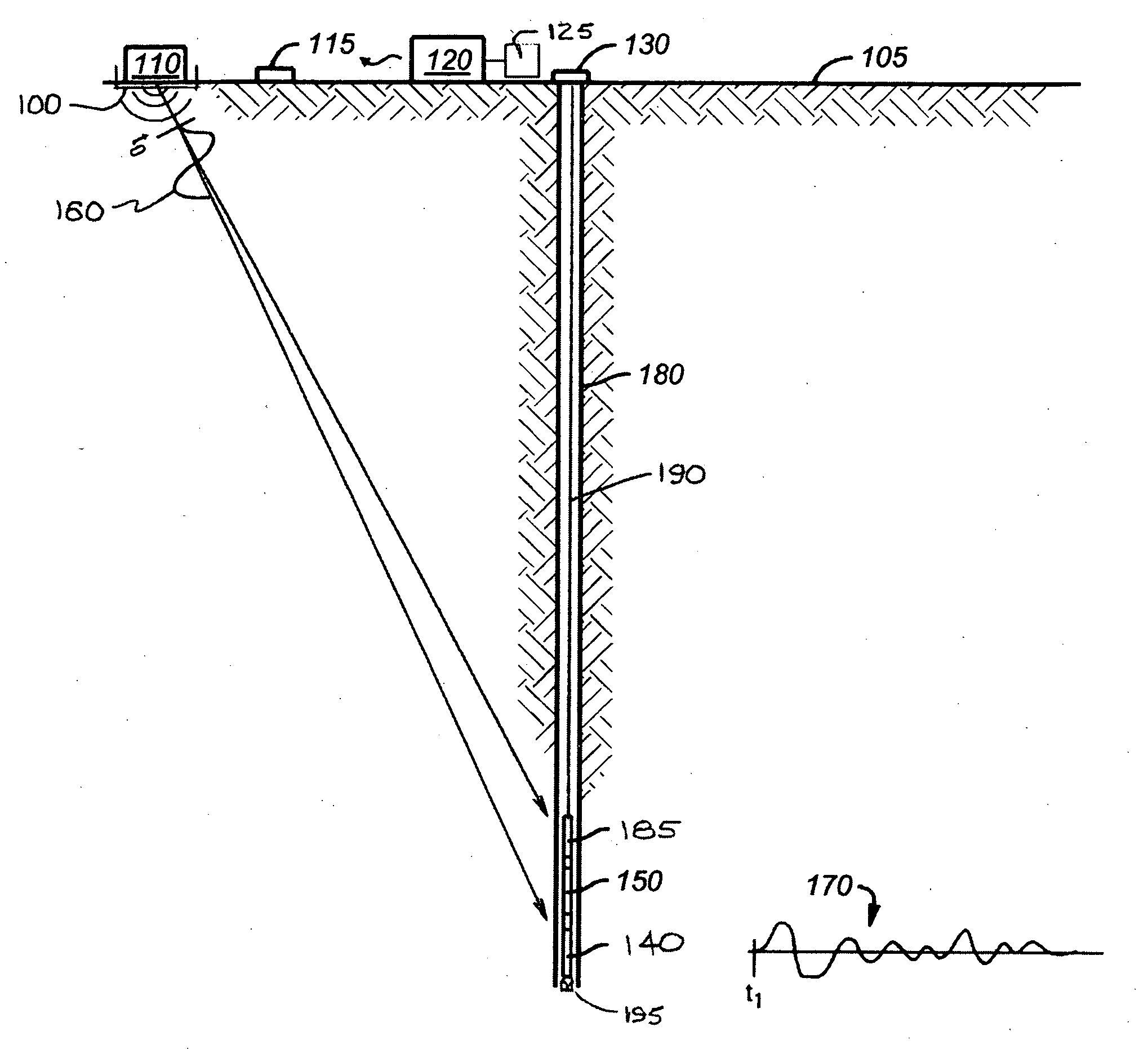
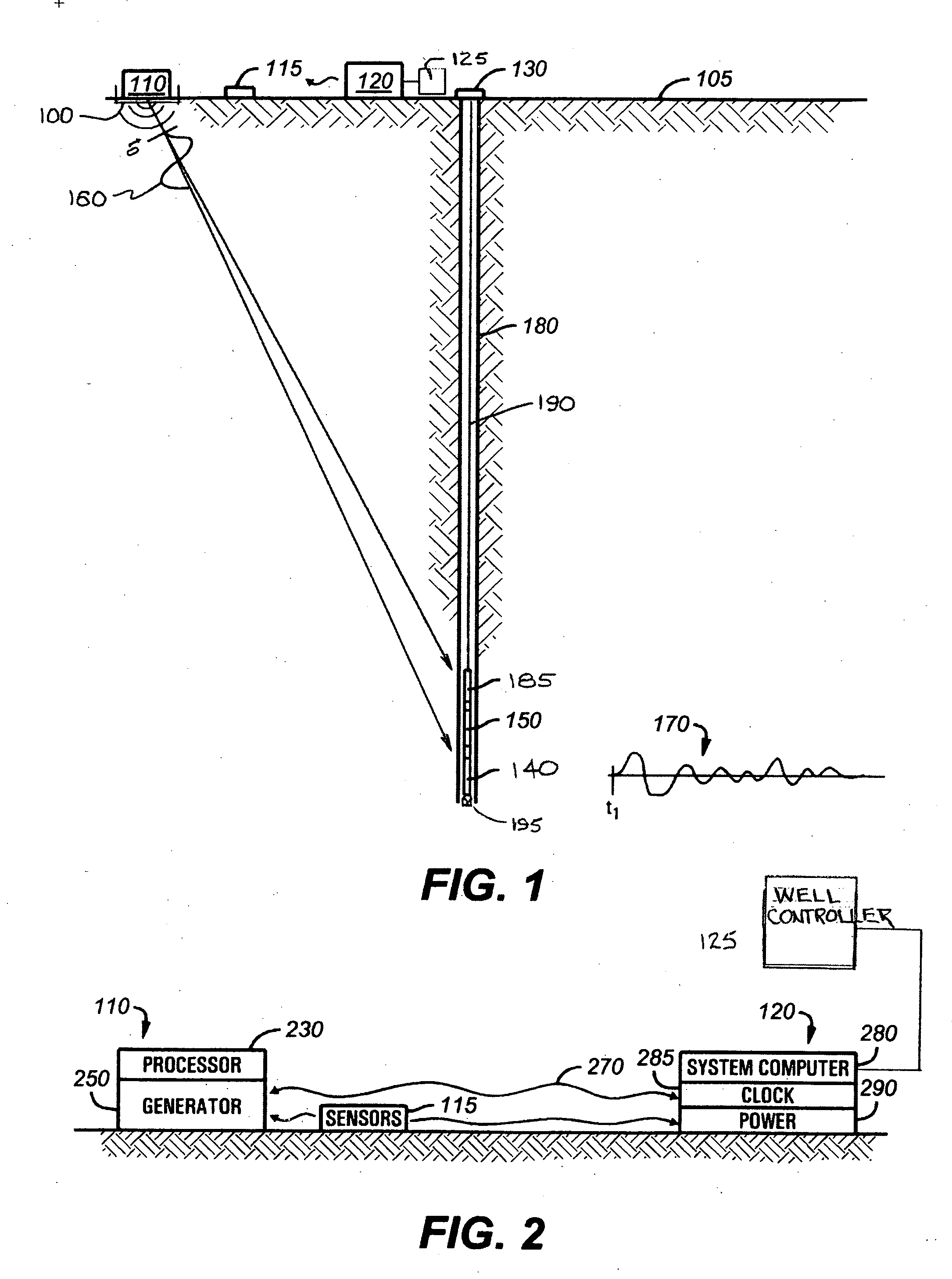
paragraph of this section, a synchronization problem has limited the effectiveness and value of VSP surveys conducted with the VSP receiver incommunicado with the surface (except for limited uphole communication via mud pulse
telemetry).
A post mission re-synchronization allows measurement of total
clock drift during the downhole episode and estimates of drift at intermediate times can be interpolated; however this is not sufficiently accurate as the drift rate may not have held constant throughout the downhole mission.
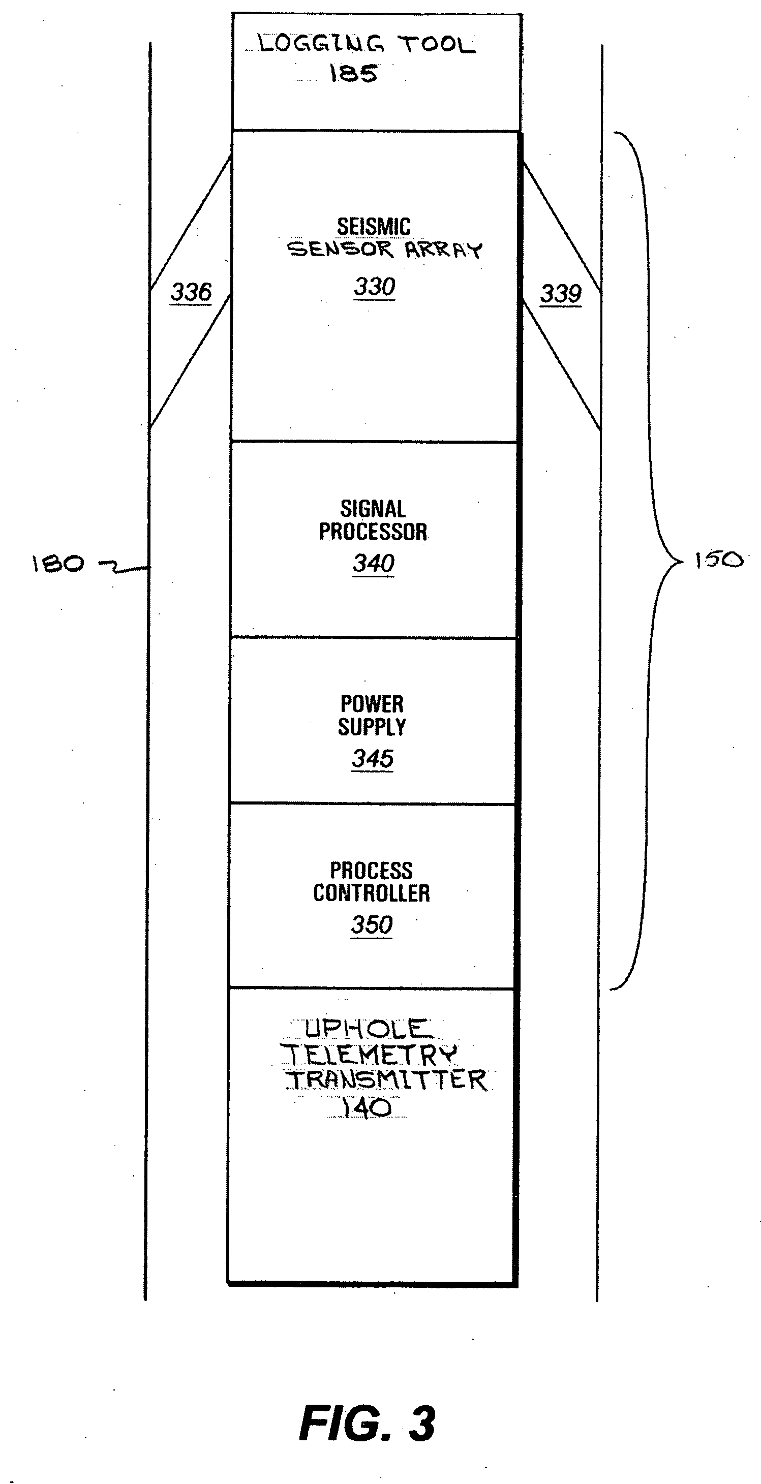
However the downhole clock has limitations imposed because of the environment in which it must operate.
Extremes of pressure and temperature in which it must continue to operate with high precision, physical constraints of the deep borehole environment, along with a potentially limited
power budget for lengthy downhole missions, have mandated that a clock with less precision than desired must be chosen.
While a precision of 10 to the minus 8th power would be considered sufficiently precise for most applications it is not sufficiently precise for the VSP application because it would mean that an error of 1
millisecond could build up in 28 hours.
Although the '595 procedure accomplishes synchronization, it suffers from precision problems (2 msec) and requires additional equipment (the pinger and pinger-receiver at the surface and downhole).
The pinger may not provide sufficient
signal strength to allow detection of the reflected pulse and may risk damage to the
pipe near the well head that is pinged.
Limitations of this solution are accuracy of the acoustic
travel time assumption, ability to receive the acoustic signals at significant depth and requirement for the acoustic
system (additional equipment and operational considerations).

