Vertical seismic profiling method utilizing seismic communication and synchronization

a technology of seismic communication and synchronization, applied in the field of while drilling vertical seismic profiling (vsp) methods and equipment, can solve the problems of insufficient accurate time-keeping in the downhole tool, new methods have suffered from limitations, and the error accumulation of seismic travel time measurements can be very detrimental to the vsp processing and resultan

Inactive Publication Date: 2009-01-08
HARMON JERALD L
View PDF19 Cites 23 Cited by
  • Summary
  • Abstract
  • Description
  • Claims
  • Application Information

AI Technical Summary

Benefits of technology

[0026]A preferred embodiment of the invention is a while-drilling VSP system suitable to utilize seismic energy generated by a surface source to (1) communicate information to a VSP receiver located near to the drill bit while the same seismic energy (in the form of seismic shots or pulses) provides (2) a re-synchronization means to correct the downhole clock associated with the VSP receiver to the master clock at the surface and also provides in the same shots (3) seismic data required for the VSP survey. The VSP receiver contains a processor that may also be linked to other while-drilling logging tools or other controllable devices near the drill bit so that commands can be transmitted from the surface and conveyed via the VSP receiver's processor to the associated tools. The associated tools if suitably configured can thus alter their operations in response to instructions transmitted via seismic signals from the surface.
[0029]Cross-correlation is applied to recorded data using a reference function that may be formed by combining other potential or known shots from the same or an adjacent receiver position and initiated from the same source location. The cross-correlation is analyzed to determine presence / absence of signal from the potential shot and to measure any time delay used for communication. A best rendition of the seismic signal for the current receiver location is formed by combining the detected shots for the location. Iterations of cross-correlation and reference-forming may be applied yielding successively more accurate and noise-free estimates of travel time and deliberately imposed delays as well as improved representations of seismic energy for VSP analysis.
[0030]Other means may be utilized to augment the seismic shot communication. The drill string may be rotated in a special on / off sequence or pumping of borehole fluid may be turned off and on in a predetermined sequence. These augmentary methods are very much poorer in signal bandwidth compared to seismic but can be useful for sending simple messages under high ambient noise and weak seismic signal conditions. The augmentary methods may be used separately or in combination with each other and with the seismic shots.

Problems solved by technology

However, these new methods have suffered from limitations.
One important limitation is the lack of sufficiently accurate time-keeping in the downhole tool: as the downhole clock drifts relative to the master clock at the surface, error accumulates in the seismic travel time measurements that can be very detrimental to the VSP processing and resultant geologic information.
Typically, prior art methods have been limited to time-keeping within about 2 milliseconds of true time.
However this technique does not always work effectively.
However, when a drilling operation is underway it is inconvenient or impractical to provide these physical linkages from the surface to devices deep in the borehole via the drill string.
However, this method is subject to limitations imposed by highly-resistive rock formations and by deep boreholes.
Electromagnetic noise may also prevent successful communication.
Hardware in the wellbore such as surface casing and the drill string may interfere with signal reception.
Deep boreholes imply high temperature and high pressure conditions, as well as requiring longer signal transmission distances and are not amenable to the application of existing electromagnetic communication systems.
As mentioned in the opening paragraph of this section, a synchronization problem has limited the effectiveness and value of VSP surveys conducted with the VSP receiver incommunicado with the surface (except for limited uphole communication via mud pulse telemetry).
A post mission re-synchronization allows measurement of total clock drift during the downhole episode and estimates of drift at intermediate times can be interpolated; however this is not sufficiently accurate as the drift rate may not have held constant throughout the downhole mission.
However the downhole clock has limitations imposed because of the environment in which it must operate.
Extremes of pressure and temperature in which it must continue to operate with high precision, physical constraints of the deep borehole environment, along with a potentially limited power budget for lengthy downhole missions, have mandated that a clock with less precision than desired must be chosen.
While a precision of 10 to the minus 8th power would be considered sufficiently precise for most applications it is not sufficiently precise for the VSP application because it would mean that an error of 1 millisecond could build up in 28 hours.
Although the '595 procedure accomplishes synchronization, it suffers from precision problems (2 msec) and requires additional equipment (the pinger and pinger-receiver at the surface and downhole).
The pinger may not provide sufficient signal strength to allow detection of the reflected pulse and may risk damage to the pipe near the well head that is pinged.
Limitations of this solution are accuracy of the acoustic travel time assumption, ability to receive the acoustic signals at significant depth and requirement for the acoustic system (additional equipment and operational considerations).

Method used


Image

  • Vertical seismic profiling method utilizing seismic communication and synchronization
  • Vertical seismic profiling method utilizing seismic communication and synchronization
  • Vertical seismic profiling method utilizing seismic communication and synchronization

Examples


Embodiment Construction

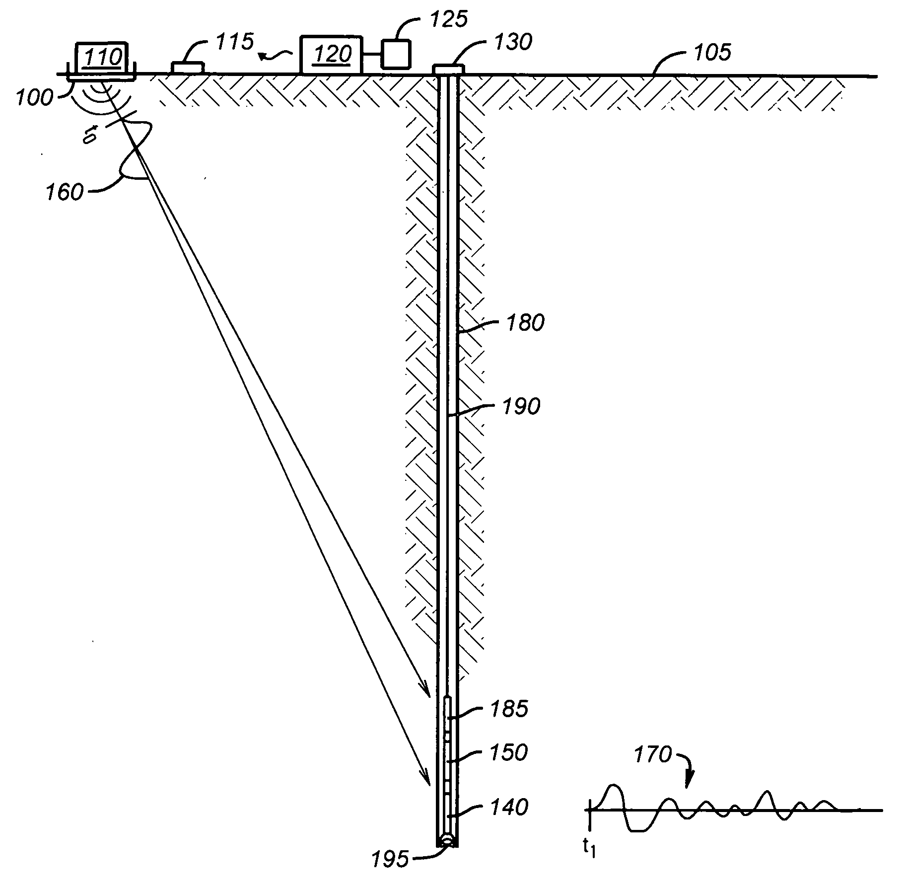
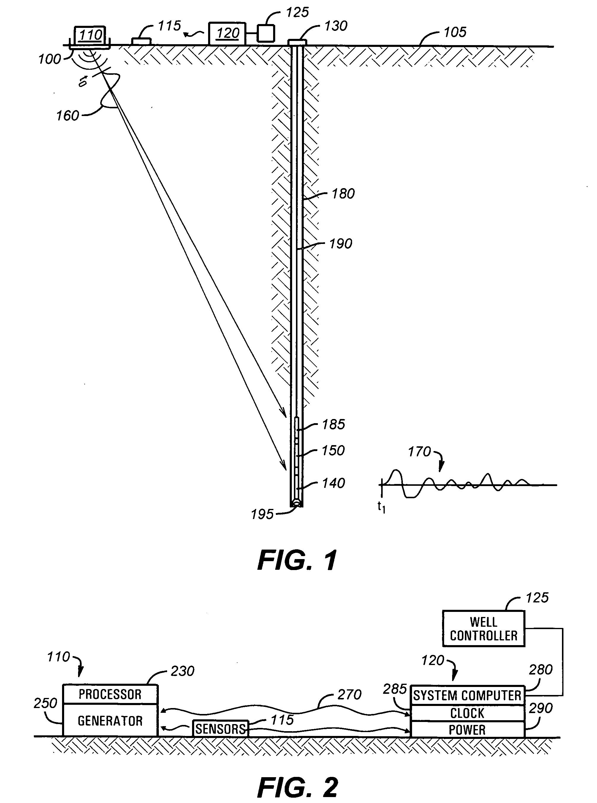
[0054]Referring to FIG. 1, a borehole 180 contains a drilling string assembly 190 connected to a wellhead equipment ensemble 130. A controllable while-drilling VSP seismic receiver / processor tool 150 (called VSP receiver in this document) is located deep in the borehole 180 at the lower end of the drilling string assembly 190. At the or near the earth's surface 105, a repeatable seismic source system 110 (called seismic source hereafter) is located at a fixed site 100. Seismic source 110 generates seismic signals 160 in response to commands from a VSP system controller 120. Seismic-sensor system 115 monitors the seismic signals 160 and any seismic emanations from the vicinity of the borehole.

[0055]VSP system controller 120 provides an operable interface between the seismic source 110 and a surface operator. In the preferred embodiment, the VSP system controller accepts commands from the operator such as by a keyboard or data entry link. The VSP system controller then executes the co...


PUM


Abstract

A while-drilling Vertical Seismic Profiling (VSP) data acquisition system utilizing the same seismic shots for three purposes is disclosed. First, the seismic shots provide a means for synchronizing a downhole clock in the VSP receiver to a master clock at the surface, thereby enabling correct determination of seismic travel times. Second, the same seismic shots are also used to communicate commands and other information to the downhole VSP receiver, such commands controlling the actions of the VSP receiver or associated devices. Third, the same seismic shots are utilized for purposes of the VSP survey itself, i.e. determination of seismic travel times, forming of seismic images, and determination of geologic and formation fluid properties using the VSP methods.

Description

CROSS-REFERENCE TO RELATED APPLICATIONS[0001]This Application is a division of application Ser. No. 11 / 370,620 filed Mar. 8, 2006. Said application Ser No. 11 / 370,620 claims the benefit of U.S. Provisional Application No. 60 / 660,026 Filed Mar. 9, 2005.BACKGROUND OF THE INVENTION[0002]1. Field of the Invention[0003]The present invention relates to novel while-drilling Vertical Seismic Profiling (VSP) methods and equipment. One aspect of the invention pertains to measuring and correcting the drift of a downhole clock associated with the VSP receiver in the borehole. Another aspect relates to communication from the surface to while-drilling logging tools in a borehole and to the control of these tools by commands and information sent from the surface by seismic signals and / or by special utilization of surface controllable drilling processes.[0004]2. Description of Related Art[0005]Those in the petroleum industry are increasingly concerned with ‘logging-while-drilling’ (LWD) or ‘measuri...

Claims


Application Information

Patent Timeline
Patent Type & Authority Applications(United States)
IPC IPC(8): G01V1/48E21B47/16
CPCG01V2210/161G01V1/42
Inventor HARMON, JERALD I.
Owner HARMON JERALD L
Why Eureka
Try Eureka