System and method for selective memory module power management

a memory module and power management technology, applied in the field of computer memory systems, can solve the problems of the number of idle states to be observed to maintain memory module power consumption, and achieve the effects of reducing power states, limiting memory module usage, and reducing responsiveness of memory modules

Inactive Publication Date: 2006-09-14
ROUND ROCK RES LLC
View PDF99 Cites 94 Cited by
  • Summary
  • Abstract
  • Description
  • Claims
  • Application Information

AI Technical Summary

Benefits of technology

[0014] A memory module is equipped with means to monitor utilization of the memory module. Through these devices, system utilization of the memory module can be monitored by tracking actual system usage, such in the form of read and write commands issued to the memory module, or by measuring temperature changes that indicate a nominal level of read and write activity beyond continual refresh activity. According to one aspect of the invention, control logic on the memory module directs the memory module into a power saving mode after determining, responsive to current activity levels, that the module need not remain immediately ready to process memory commands. In accordance with another aspect of the invention, the control logic could throttle activity of the memory module to reduce the responsiveness of the memory module in the face of receiving more than a desired number of system commands per unit time and / or measured temperature levels or changes. In such a mode, the memory module would not be rendered dormant to system operations as in the previously described aspect of the invention, but instead would merely limit memory module usage and allow the memory module to process only a predetermined number of system commands or remain at or below a certain operating temperature. For example, the control logic would cause a number of idle states to be observed to maintain memory module power consumption below a certain level.
[0015] According to another aspect of the invention, data packets summarizing the memory module's activity level are transmitted on the memory bus via the memory hub. The memory module activity level packet could be received by a memory controller or by a master memory hub disposed on another memory module. Selectively directing memory modules into a reduced power state can thereby be managed centrally by the system controller, the memory controller, or a master memory module equipped with a master module power management controller. The system controller or master module power management controller may also communicate power control data packets to other memory modules via the system bus and the other memory modules'memory hubs to direct those modules into reduced power states. The system controller or master module power management controller could direct the memory modules into a power saving mode such as a self-refresh mode, could throttle memory module activity to reduce responsiveness and reduce power consumption, or use another reduced power mode.

Problems solved by technology

For example, the control logic would cause a number of idle states to be observed to maintain memory module power consumption below a certain level.

Method used


Image

  • System and method for selective memory module power management
  • System and method for selective memory module power management
  • System and method for selective memory module power management

Examples


Embodiment Construction

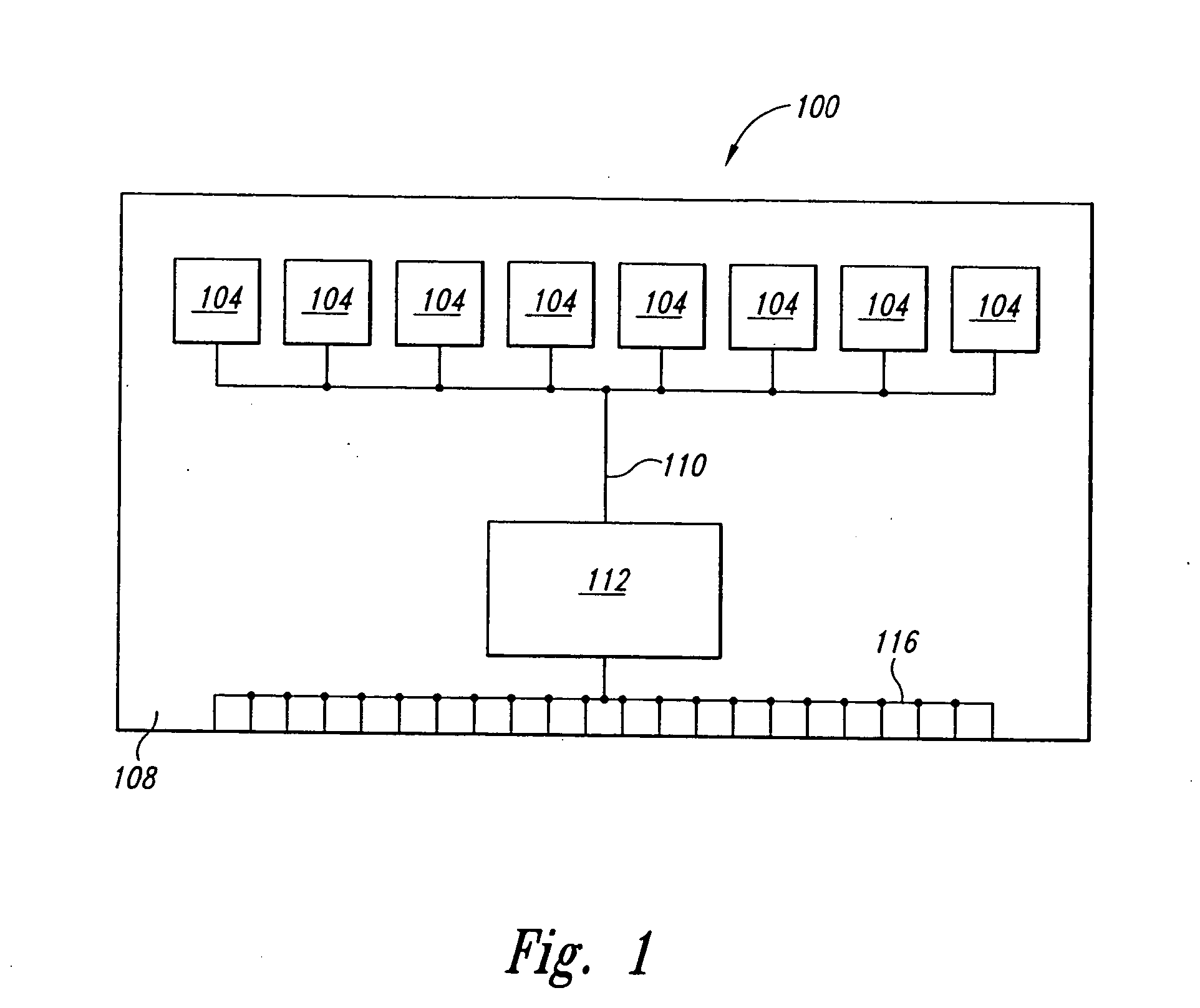
[0022]FIG. 3 shows a memory module 300 equipped with activity monitoring and power saving capabilities employing a first embodiment of the present invention. The memory module 300 comprises a plurality of memory devices 104 mounted on a substrate 108 through which the DRAM devices 104 are operably coupled to a memory hub 312 through communications lines 110 such as conductive traces or other similar signal carrying devices. The memory module shown in FIG. 3 comprises most of the same components used in the memory module shown in FIG. 1 thus, in the interest of brevity, these components have been provided with the same reference numerals, and an explanation of their functions and operations will not be repeated.

[0023] The memory module 300 shown in FIG. 3 comprises three additional devices not included in the conventional memory module of FIG. 1. The memory module 300 includes an activity monitor 350, a power management controller 360, and a temperature sensor 370, the last being co...


PUM


Abstract

A memory module includes a memory hub that monitors utilization of the memory module and directs devices of the memory module to a reduced power state when the module is not being used at a desired level. System utilization of the memory module is monitored by tracking system usage, manifested by read and write commands issued to the memory module, or by measuring temperature changes indicating a level of device activity beyond normal refresh activity. Alternatively, measured activity levels can be transmitted over a system bus to a centralized power management controller which, responsive to the activity level packets transmitted by remote memory modules, direct devices of those remote memory modules to a reduced power state. The centralized power management controller could be disposed on a master memory module or in a memory or system controller.

Description

TECHNICAL FIELD [0001] This invention relates to computer memory systems. More particularly, the present invention relates to enhancing power management and reducing power consumption in a computer memory system. BACKGROUND OF THE INVENTION [0002] Most computers and other digital systems have a system memory which often consists of dynamic random access memory (“DRAM”) devices. DRAM devices are fairly inexpensive because a DRAM memory cell needs relatively few components to store a data bit as compared with other types of memory cells. Thus, a large system memory can be implemented using DRAM devices for a relatively low cost. [0003] Commonly, DRAM devices are arranged on memory modules, such as single in-line memory modules (“SIMMs”) and dual in-line memory modules (“DIMMs”). A representative module is shown in FIG. 1. The module 100 features a number of DRAM devices 104 mounted on an insulative substrate 108 through which the DRAM devices 104 are operably coupled through communica...

Claims


Application Information

Patent Timeline
Patent Type & Authority Applications(United States)
IPC IPC(8): G06F1/32G06F1/20G06F1/26
CPCG06F1/206G06F1/3225G06F1/3275Y02B60/1228Y02B60/1275Y02B60/32Y02B60/1225Y02D10/00Y02D30/50
Inventor JEDDELOH, JOSEPH M.LEE, TERRY
Owner ROUND ROCK RES LLC
Why Eureka
Try Eureka