Internal pressure controller of chamber and internal pressure subject -to- control type chamber

a technology of internal pressure controller and controller, which is applied in the direction of fluid pressure control, process and machine control, instruments, etc., can solve the problems of high equipment cost and operating cost of running the vacuum chamber e, difficult to achieve cost reduction with this system, and high manufacturing cost, etc., to achieve accurate and fast adjustment, easy adjustment, and accurate flow rate control

Inactive Publication Date: 2006-09-21
FUJIKIN INC +1
View PDF11 Cites 161 Cited by
  • Summary
  • Abstract
  • Description
  • Claims
  • Application Information

AI Technical Summary

Benefits of technology

[0021] Using an internal pressure controller of the chamber, accurate flow rate control can be achieved over a wide flow rate range because the internal pressure controller serves to divide a required flow rate range into a plurality of smaller flow rate ranges, thus allowing a small flow quantity, i.e., less than 10% of a maximum flow rate, to be controlled by a pressure type flow controller for controlling a small flow quantity.
[0022] Also, because of superimposition of flow rate control by means of pressure type flow controllers allotted for all of the flow rate ranges, the flow rate of gas supplied to the chamber can be controlled continuously due to the feature of superimposed flow rate control wherein the rate of rise of a control signal has imposed limitations.
[0023] As a result, the flow rate of gas supplied to the chamber can be adjusted accurately and quickly, thus allowing an internal pressure of the chamber to be easily adjusted and maintained at a specified set pressure. Thus, the need for a conventional automatic pressure controller APC can be eliminated, and facility costs for constructing an evacuation system for the chamber can be substantially reduced. Also, the vacuum pump utilized, in accordance with the present invention, is one having an exhaust volume large enough to reach the lowest specified pressure of the chamber. This means that unlike a conventional evacuation system of a chamber, it is not necessary that the vacuum pump, in accordance with the present invention, to have a considerable excess margin for evacuation volume. Accordingly, a considerable cost reduction of the evacuation system becomes possible as well.

Problems solved by technology

However, this exhaust system, for which one vacuum pump having a large exhaust volume and large compression ratio is used, has disadvantageously high manufacturing costs and the like, so it is not popular.
Accordingly, equipment costs and operating costs of running the vacuum chamber E are high, so it is difficult to achieve reduction of costs with this system.
This results in problems such as a low operating rate of the process chamber, which leads to unevenness in quality of treated products because too much time is needed for adjusting the internal pressure of the chamber due to so-called “poor pressure control responsivity.”
However, various difficulties with this type of fluid supply facility have been found.
As a result, accurate flow rate control cannot be expected in the small flow quantity range, which is less than 100 SCCM.

Method used


Image

  • Internal pressure controller of chamber and internal pressure subject -to- control type chamber
  • Internal pressure controller of chamber and internal pressure subject -to- control type chamber
  • Internal pressure controller of chamber and internal pressure subject -to- control type chamber

Examples


first embodiment

The First Embodiment

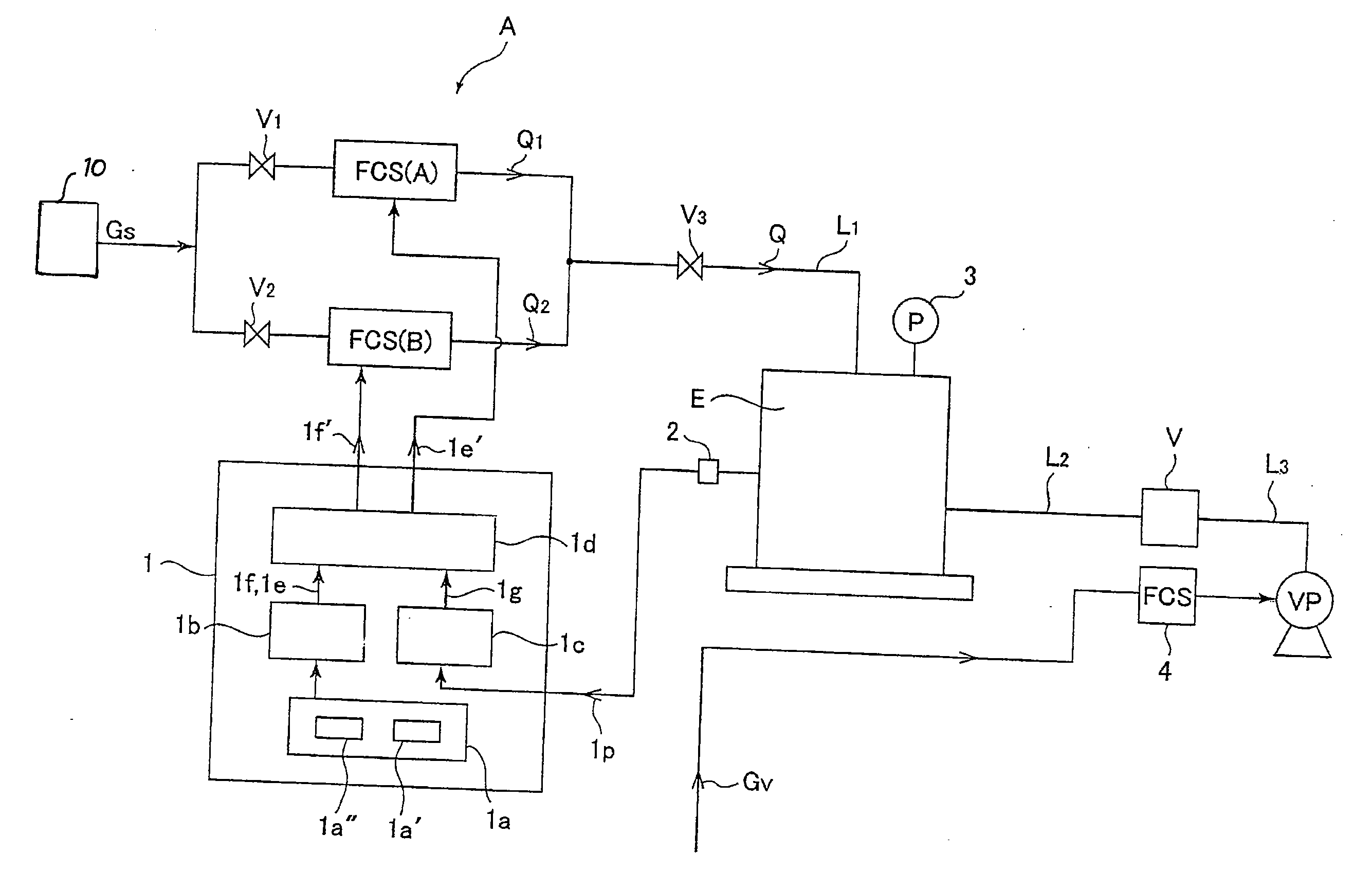
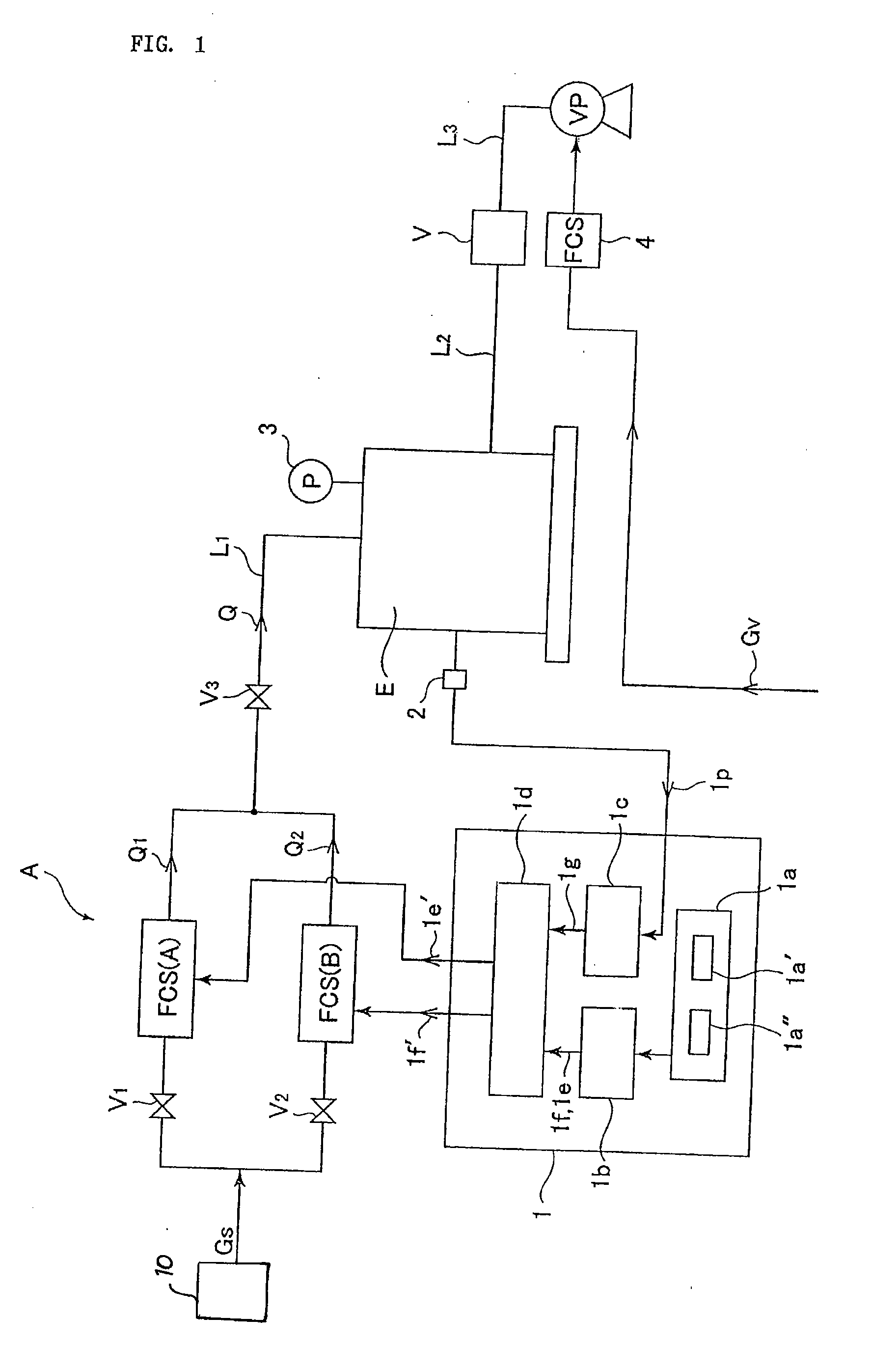
[0061]FIG. 1 illustrates the first non-limiting embodiment of an internal pressure controller of a chamber, according to the present invention, which shows basic structure of the internal pressure controller. As shown in FIG. 1, A designates a gas supply facility, Gs designates a supply gas from a supply gas input part 10, FCS(A) designates a pressure type flow controller for a small flow quantity, FCS(B) designates a pressure type flow controller for a large flow quantity, E designates a process chamber, P designates pressure inside chamber E, Q1 designates a control flow rate of the pressure type flow controller FCS(A) for a small flow quantity, Q2 designates a control flow rate of the pressure type flow controller FCS(B) for a large flow quantity, Q designates a supply flow rate to chamber E, V designates an adjustment valve, VP designates a vacuum pump, V1-V3 designate control valves, L1 designates a gas supply pipe, L2-L3designates exhaust pipes, 1 designate...


PUM


Abstract

A gas supply facility includes a plurality of pressure type flow controllers connected in parallel, and a first controller to control operation of the plurality of pressure type flow controllers so as to supply a desired gas exhausted by a vacuum pump to a chamber while controlling its flow rate, one of the pressure type flow controllers operates as a second controller to control the gas flow rate range up to 10% of the maximum flow rate supplied to the chamber, while the remaining pressure type flow controllers are made to be ones that control the rest of the gas flow rate range. Furthermore, pressure inside the chamber is controlled by installing a pressure detector in the chamber, inputting the value detected by the detector to the controller, and by adjusting a control signal to the pressure type flow controllers.

Description

[0001] This is a National Phase Application in the United States of International Patent Application No. PCT / JP2004 / 013368 filed Sep. 14, 2004, which claims priority on Japanese Patent Application No. 2003-346497, filed Oct. 6, 2003. The entire disclosures of the above patent applications are hereby incorporated by reference.FIELD OF THE INVENTION [0002] The present invention is concerned with an internal pressure controller of a chamber and an internal pressure subject-to-control type chamber utilized with semiconductor manufacturing facilities and the like. BACKGROUND OF THE INVENTION [0003] In recent years, gas supply facilities equipped with a so-called “pressure type flow controller” to be employed for a gas supply facility to a process chamber have been widely used with semiconductor manufacturing facilities and the like. [0004]FIG. 8 illustrates one example. It is so constituted that pressure type flow controllers C1, C2 and C3 and fluid switching valves D1, D2 and D3 are pro...

Claims


Application Information

Patent Timeline
Patent Type & Authority Applications(United States)
IPC IPC(8): A62B31/00A61G10/00G05D16/20G05D7/06
CPCG05D16/208Y10T137/87507Y10T137/8741Y10T137/7761G05D7/00
Inventor OHMITERAMOTO, AKINOBUUNO, TOMIODOHI, RYOUSUKENISHINO, KOUJINAKAMURA, OSAMUMATSUMOTO, ATSUSHINAGASE, MASAAKIIKEDA, NOBUKAZU
Owner FUJIKIN INC
Why Eureka
Try Eureka