These electronic devices have been traditionally fabricated using
silicon (Si) as a light-absorbing, semiconducting material in a relatively expensive production process.
A central challenge in constructing a CIGS-based
solar cell is that the components of the CIGS layer must be within a narrow stoichiometric ratio in order for the resulting
cell to be highly efficient.
Achieving precise
stoichiometric composition over relatively larger substrate areas is however difficult using traditional vacuum-based deposition processes.
For example, it is difficult to deposit compounds and / or alloys containing more than one element by
sputtering or
evaporation.
Both techniques rely on deposition approaches that are limited to line-of-
sight and limited-area sources, tending to result in poor surface coverage.
Line-of-
sight trajectories and limited-area sources can result in the non-uniform three-dimensional distribution of elements in all three dimensions and / or poor film-thickness uniformity over large areas.
Such non-uniformity also alters the local stoichiometric ratios of the absorber layer, decreasing the potential power conversion efficiency of the complete device.
However, solar cells fabricated using the sintered layers had very low efficiencies because the structural and electronic quality of these absorbers were poor.
A difficulty in this approach was finding an appropriate fluxing agent for dense CulnSe2 film formation.
Solar cells made in this manner also had poor conversion efficiencies.
Porous
solar cell absorbers yield unstable devices because of the large internal surface area within the device, and small grains limit the conversion efficiency of solar cells.
Another key limitation of this method was the inability to effectively incorporate
gallium into the material.
The absence of
gallium decreases the potential power conversion efficiency of the
solar cell.
In practice, while
gallium oxide particles can easily be produced, it is very difficult to reduce
gallium oxide, even at relatively high temperatures, and in the absence of reduction,
gallium oxide cannot be effectively used as a precursor material for gallium in the final film.
Accordingly, in addition to poor stability, solar cells made using the approach of Basol et al. had sub-optimal power conversion efficiency.
A
disadvantage of solar
cell devices comprised of thin-film absorber layers formed in this manner was the poor reproducibility of the resulting device performance, and the porous form of the absorber layer, which tends to result in poor device stability.
The lack of a means to incorporate additional Ga beyond that possible through a
solid-solution (containing either Cu+ Ga or In+Ga) restricts the potential performance of a device constructed by this method.
In particular, since the presence of additional gallium in the light absorbing film can serve both to widen the bandgap of the
semiconductor material and to increase the
open circuit voltage of the solar
cell, a lack of additional gallium in the light-absorbing thin film tends to decrease the potential power conversion efficiency of solar cells created in this manner.
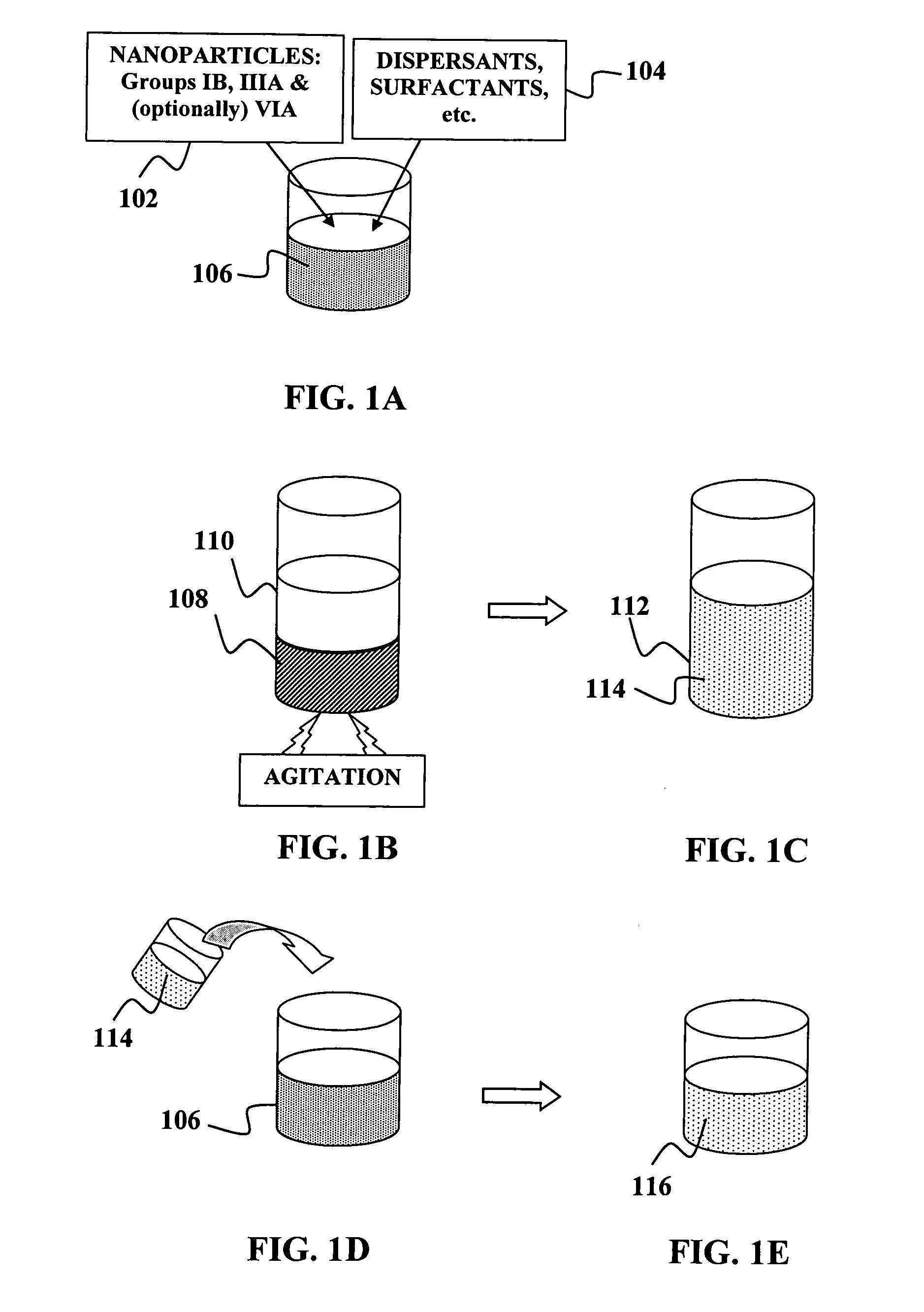
However, no technique was known in the prior art to create gallium
nanoparticle powders sufficient and adequate for
semiconductor applications, in part because gallium is molten near
room temperature and therefore does not lend itself to common techniques for creating nanoparticles in the form of powders that are then dispersed in solution (as is commonly done with the other elements).
As a result, it was not possible to directly incorporate gallium (or incorporate gallium in a high percentage) into a metallic dispersion used to print the CIG precursor of a CIGS solar cell.
However, this approach results in a compound film without an intentionally graded bandgap.
Further, a relatively high level of Ga in the middle of the CIGS absorber layer tends to negatively
impact device function, as small CuGaSe2 grains form.
However, this device was formed on a relatively small substrate, and the compound film was formed over a relatively long time.
This fabrication method does not provide an efficient approach for high-volume solar cell production.
Further, as described above, there are several challenges and disadvantages associated with
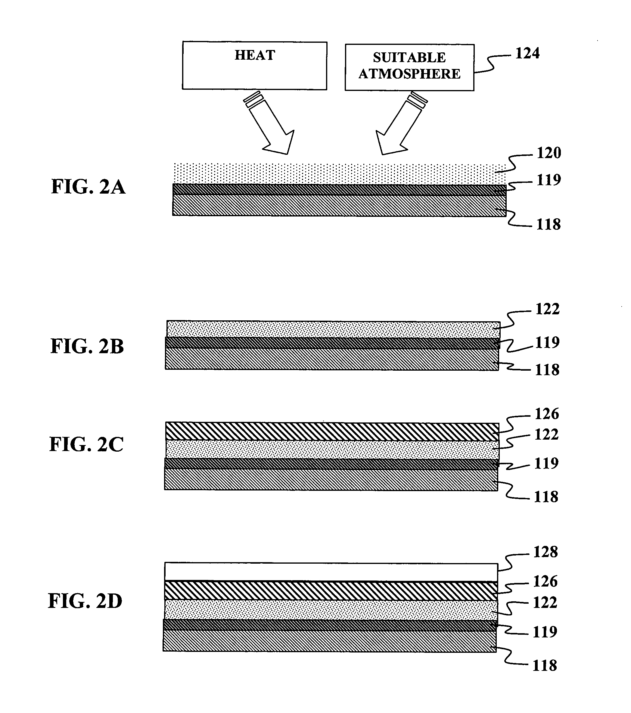
evaporation or other vacuum-based deposition techniques for the CIGS absorber layer, including but not limited to (a) relatively high production cost, (b) relatively poor spatial and chemical uniformity of deposited compound films, and (c) relatively low
throughput, limiting the potential for high-volume production.
Moreover, the creation of a bandgap graded absorber layer using evaporative sources requires a relatively expensive real-time
monitoring system to assess the relative composition of the absorber layer as it is being constructed.

