Ultra wideband antenna for filtering predetermined frequency band signal and system for receiving ultra wideband signal using the same

a wideband antenna and predetermined frequency band technology, applied in the direction of slot antennas, antenna details, antennas, etc., can solve the problems of complex system construction and large power loss, and achieve the effect of improving power loss and noise characteristics

Active Publication Date: 2006-09-21
SAMSUNG ELECTRONICS CO LTD
View PDF11 Cites 17 Cited by
  • Summary
  • Abstract
  • Description
  • Claims
  • Application Information

AI Technical Summary

Benefits of technology

[0014] Another aspect of the present invention provides a system for receiving an ultra wideband signal that is small-sized and has improved power loss and noise characteristics by using an antenna receiving ultra wideband signals except for a predetermined frequency band signal.

Problems solved by technology

Also, since many constituent elements exist in the receiving system, the power loss is great and the system construction is complicated.

Method used


Image

  • Ultra wideband antenna for filtering predetermined frequency band signal and system for receiving ultra wideband signal using the same
  • Ultra wideband antenna for filtering predetermined frequency band signal and system for receiving ultra wideband signal using the same
  • Ultra wideband antenna for filtering predetermined frequency band signal and system for receiving ultra wideband signal using the same

Examples


Embodiment Construction

[0041] Exemplary embodiments of the present invention will be described in detail with reference to the accompanying drawings. In the drawings, the same elements are denoted by the same reference numerals throughout the drawings. In the following description, detailed descriptions of known functions and configurations incorporated herein have been omitted for conciseness and clarity.

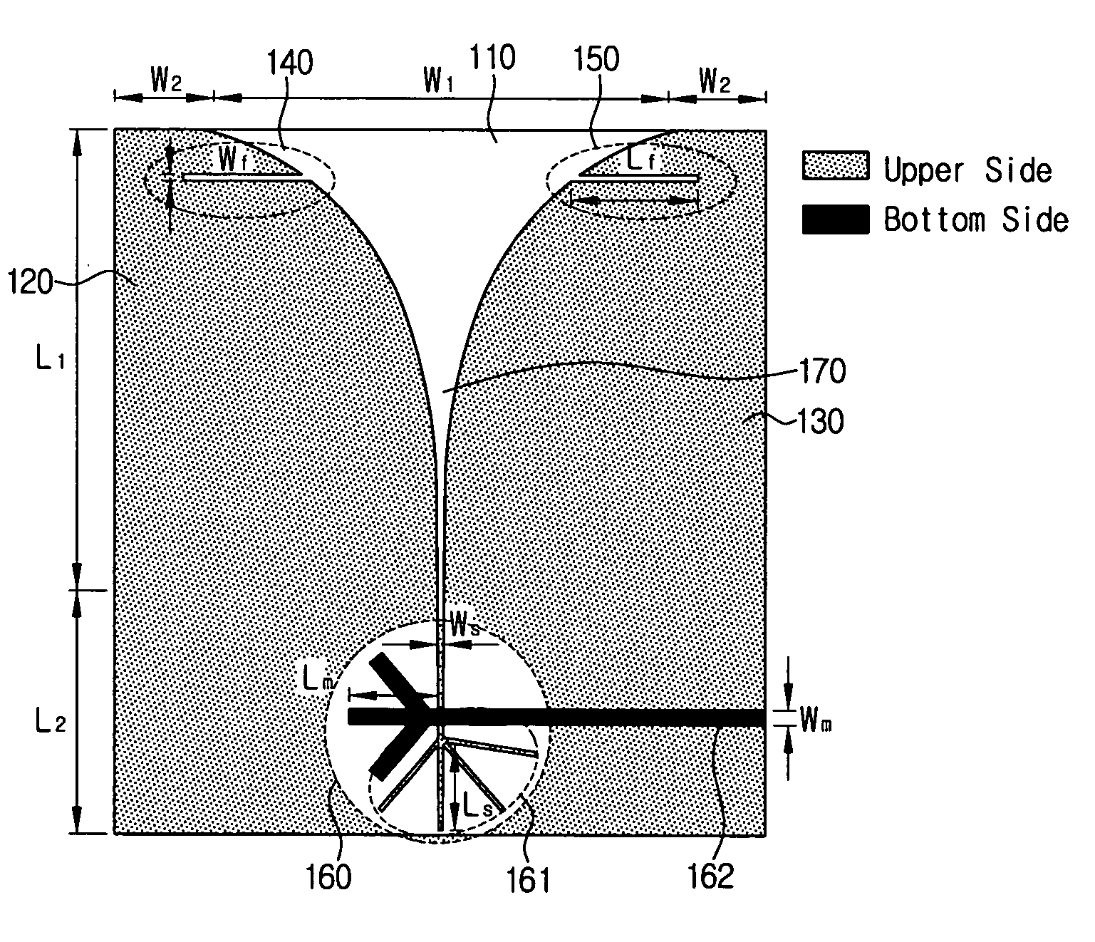
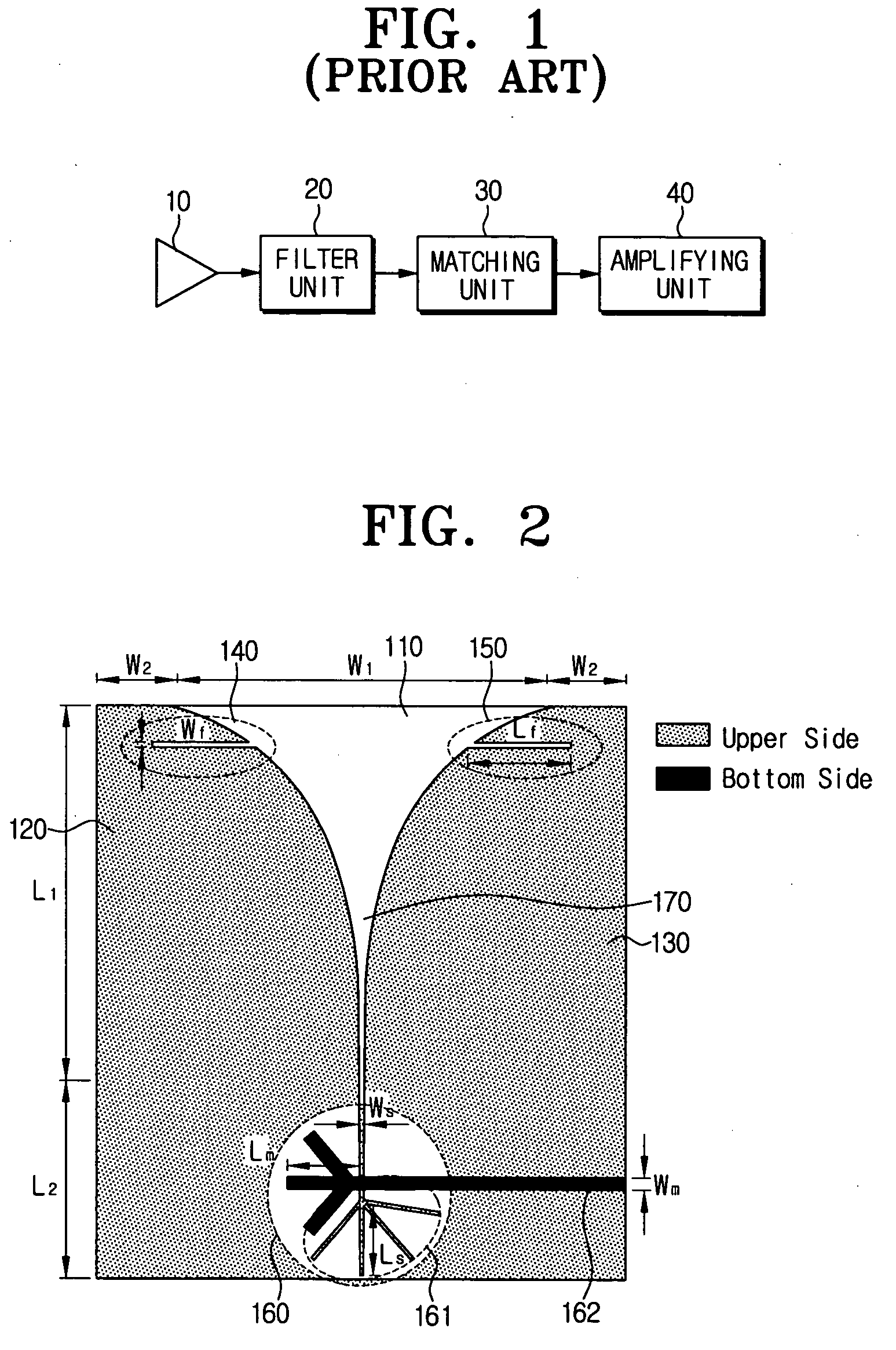
[0042]FIG. 2 is a view illustrating the structure of an ultra wideband antenna according to a first exemplary embodiment of the present invention. Referring to FIG. 2, the ultra wideband antenna according to the first exemplary embodiment of the present invention includes a substrate 110, a first metal layer 120, a second metal layer 130, a first stub 140, a second stub 150, a power feeding part 160 and a taper type slot 170.

[0043] The substrate 110 may be a typical dielectric substrate.

[0044] On the upper surface of the substrate 110, the first metal layer 120 and the second metal layer 130 are depos...


PUM


Abstract

An ultra wideband antenna is provided that filters a predetermined frequency signal. The ultra wideband antenna includes a power feeding part that receives a supply of an external electromagnetic energy; a radiator excited by the electromagnetic energy fed through the power feeding part and radiating an electromagnetic wave; and a stub, provided on the radiator in a direction parallel to a direction of an electric field formed by the electromagnetic wave, that intercepts transmission / reception of a predetermined frequency band signal. The length of the stub may be ¼ of a wavelength of the intermediate frequency of the predetermined frequency band to be removed to filter the corresponding frequency band signal. The ultra wideband antenna simplifies the construction of an ultra wideband receiving system with the power loss and noise characteristics of the system improved.

Description

[0001] This application claims priority from Korean Patent Application No. 10-2005-0017287, filed on Mar. 2, 2005 and Korean Patent Application No. 10-2005-0128930, filed on Dec. 23, 2005, in the Korean Intellectual Property Office, the disclosure of which is incorporated herein by reference. BACKGROUND OF THE INVENTION [0002] 1. Field of the Invention [0003] Apparatuses consistent with the present invention relate to an ultra wideband antenna, and more particularly to an ultra wideband antenna that intercepts transmission / reception of a predetermined frequency band signal using a radiator with a stub having a length of λ / 4 inserted thereto. [0004] 2. Description of the Related Art [0005] All antennas are used to convert an electric signal into a specified electromagnetic wave to radiate the converted electromagnetic wave to free space, or to convert a received electromagnetic wave into an electric signal. Ultra wideband (UWB) technology refers to a wireless transmission technology ...

Claims


Application Information

Patent Timeline
Patent Type & Authority Applications(United States)
IPC IPC(8): H01Q13/10
CPCH01Q1/38H01Q13/08H01Q13/10
Inventor HAN, SANG-MINKIM, YOUNG-HWANLEE, SEONG-SOOYOON, HYUNG-KUKYOON, YOUNG-JOONGLIM, YO-HANYOON, ICK-JAEKIM, HYUNG-RAK
Owner SAMSUNG ELECTRONICS CO LTD
Why Eureka
Try Eureka