
Method for manufacturing transistor in semiconductor device

a semiconductor device and manufacturing method technology, applied in the direction of semiconductor devices, light sources, electrical devices, etc., can solve the problems of deterioration of device refresh characteristics, limitations of existing planar transistor structures in realizing vt targets, etc., to improve device refresh characteristics, reduce leakage current, and increase data retention time

Inactive Publication Date: 2006-09-21
SK HYNIX INC
View PDF2 Cites 0 Cited by
  • Summary
  • Abstract
  • Description
  • Claims
  • Application Information

AI Technical Summary

Benefits of technology

[0008] Accordingly, the present invention has been made to solve the above-mentioned problems occurring in the prior method for manufacturing the transistor in the semiconductor device, and it is an object of the present invention to provide a method for manufacturing a transistor in a semiconductor device, which can inhibit the formation of depletion regions in channel regions corresponding to the sides of a gate having a recessed channel structure, so as to reduce the leakage current of the device and to increase the data retention time, thus improving the refresh characteristics of the device.

Problems solved by technology

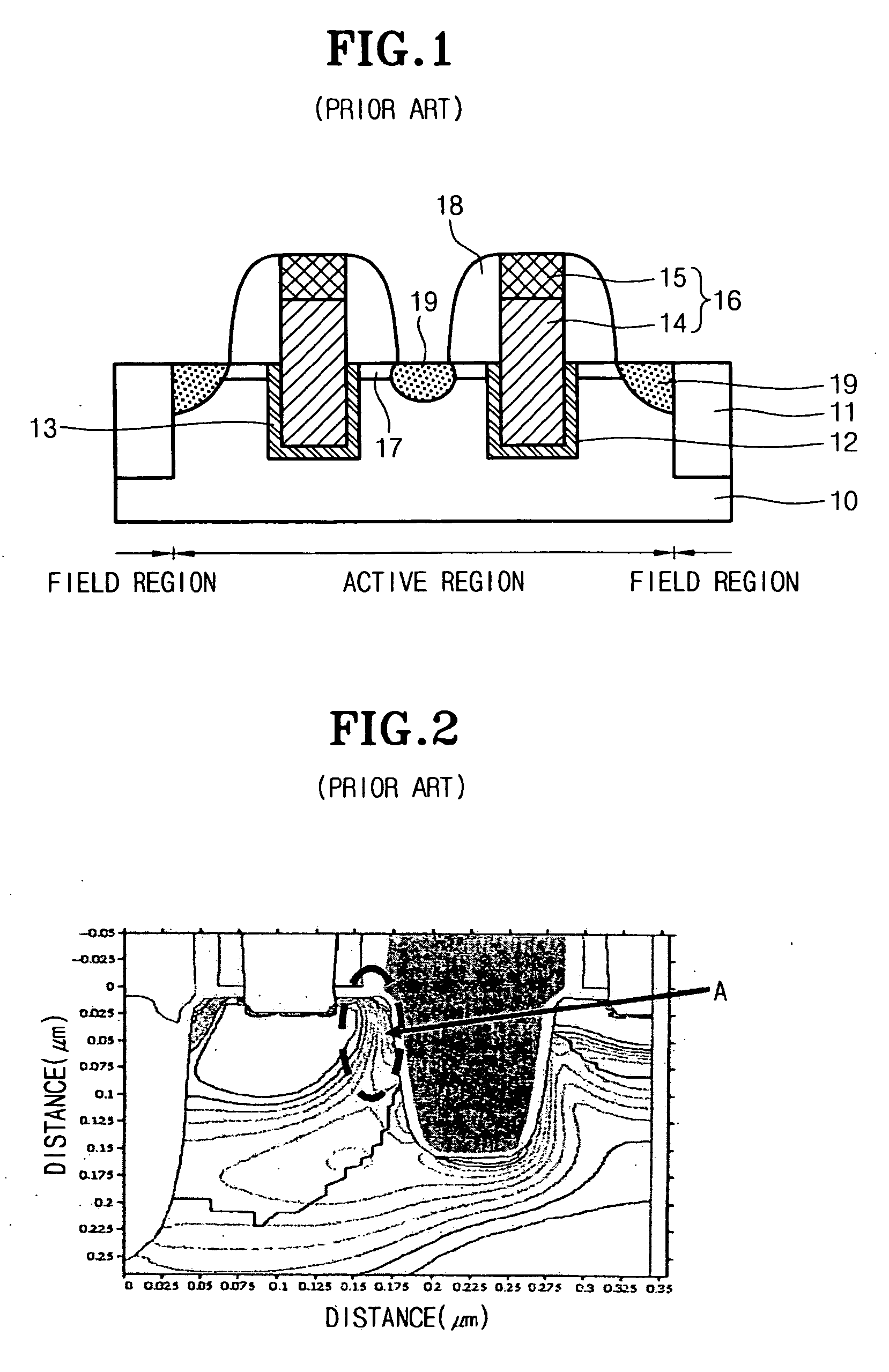
As a result, the existing planar transistor structures encounter limitations in realizing the Vt target of the cell transistor required in a specific device.
FIG. 2 shows problems occurring in the prior art and shows the simulation results for potential distribution in the cell transistor having the recessed channel structure.
Thus, the data retention time of the device is shortened, resulting in deterioration in the refresh characteristics of the device.

Method used


Image

  • Method for manufacturing transistor in semiconductor device
  • Method for manufacturing transistor in semiconductor device
  • Method for manufacturing transistor in semiconductor device

Examples


Embodiment Construction

[0038] Hereinafter, a preferred embodiment of the present invention will be described in detail with reference to the accompanying drawings.

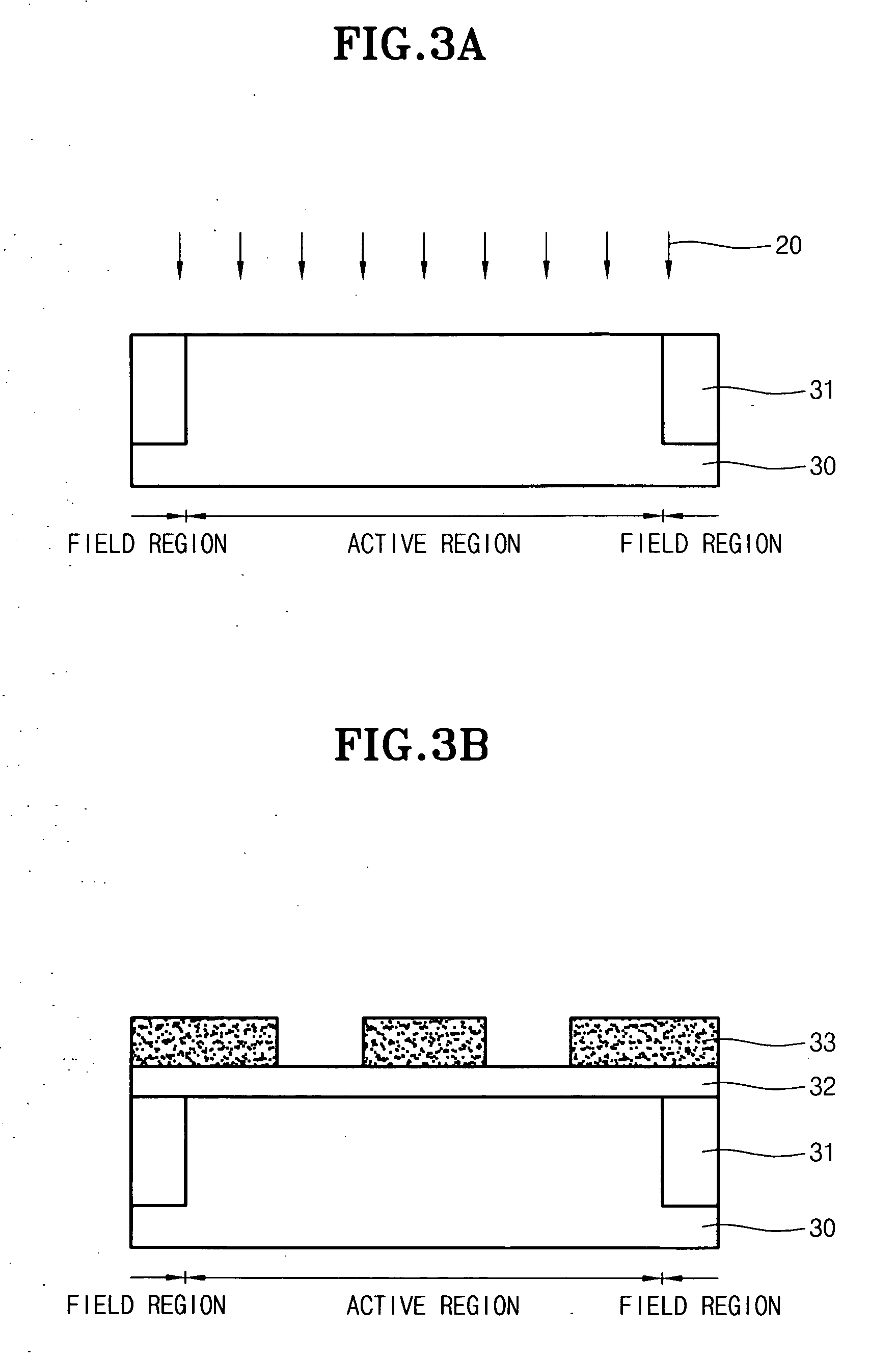
[0039]FIGS. 3a to 3g are cross-sectional views for explaining each step of a method for manufacturing a transistor in a semiconductor device according to the present invention.

[0040] As shown in FIG. 3a, the silicon substrate 30 is provided which has active and field regions defined thereon and the device isolation film 31 in the field region. Then, the resulting substrate is sequentially subjected to a well ion implantation process (not shown) and an annealing process (not shown), followed by the first channel ion implantation process 20. The first channel ion implantation process 20 is performed with an ion implantation dose of 1E12-3E13 atoms / cm2 and an ion implantation energy of 10-50 keV. Also in the first channel ion implantation process, the wafer can be tilted at an angle of 3-7° in order to minimize a channeling effect caused by ion i...


PUM


Abstract

Disclosed herein is a method for manufacturing a transistor in a semiconductor device, which can improve the refresh characteristics of the device. The method comprises the steps of: providing a silicon substrate having active and field regions defined thereon; performing a first channel ion implantation process into the silicon substrate; sequentially forming a hard mask film and a photoresist pattern exposing a gate formation region on the substrate into which the first channel ion implantation process has been performed; performing a second channel ion implantation process into the substrate at a higher concentration than that of the first ion implantation process using the photoresist pattern as an ion implantation mask, so as to form doped regions in the substrate at the gate formation region and both sides adjacent thereto; etching a hard mask film using the photoresist pattern as an etch barrier; removing the photoresist pattern; etching the substrate using a portion of the hard mask film remaining after the etching as an etch barrier, so as to form a groove; removing the hard mask film remaining after the etching; forming a gate in the groove of the substrate from which the hard mask film has been removed; and forming source and drain regions on the substrate at both sides of the gate.

Description

BACKGROUND OF THE INVENTION [0001] 1. Field of the Invention [0002] The present invention relates to a method for manufacturing a semiconductor device, and more particularly, to a method for manufacturing a transistor in a semiconductor device, which can improve the refresh characteristics of the device. [0003] 2. Description of the Prior Art [0004] Recently, as the design rule of a device pattern shrinks below 100 nm, the channel length of a cell transistor corresponding thereto is also very reduced. As a result, the existing planar transistor structures encounter limitations in realizing the Vt target of the cell transistor required in a specific device. For this reason, a method for forming a transistor with a recessed channel structure was proposed. This transistor with the recessed channel structure has a channel length secured by selectively etching a portion of the active region of a substrate, which corresponds to a region where a gate is to be formed. [0005]FIG. 1 is a cros...

Claims


Application Information

Patent Timeline
IPC IPC(8): H01L21/84H01L21/00
CPCH01L21/823412H01L21/823425H01L21/823437H01L29/66537H01L29/6659H01L29/66621H01L29/7834H05B39/09H05B41/30Y02B20/40
Inventor KIM, YONG SOOJANG, SE AUGOH, JAE GEUN
Owner SK HYNIX INC
Learn More