

Oxidation catalyst on a substrate utilized for the purification of exhaust gases
a technology of oxidation catalyst and substrate, which is applied in the direction of physical/chemical process catalyst, metal/metal-oxide/metal-hydroxide catalyst, separation process, etc., can solve the problems of serious air pollution and negative impact on human health
- Summary
- Abstract
- Description
- Claims
- Application Information
AI Technical Summary
Benefits of technology
Problems solved by technology
Method used
Image

Examples
example 1
[0039] A washcoat slurry is prepared by mixing 1200 g La-doped alumina having 9.4% lanthanum oxide, 720 g tin oxide pre-calcined at 800° C. for 8 hours and 480 g H-beta-zeolite with a silica to alumina ratio of 25 in 3 liters of water, followed by milling the mixture for 20 hours. A ceramic honeycomb substrate supplied by Corning having a diameter of 1.75″, a length of 2″, and a cell density of about 400 cpsi is dipped into the washcoat slurry. Extra slurry is blown out using an air-knife. The coated honeycomb is then dried at 125° C. for 2-3 hours and calcined at 550° C. for 3 hours. The resulting washcoat loading is 125 g / l platinum sulfite acid is deposited on the coated substrate by incipient wetness impregnation, followed by drying at 125° C. for 2-3 hours and calcination at 550° C. for 3 hours. The resulting platinum loading is 1.4 g / l.
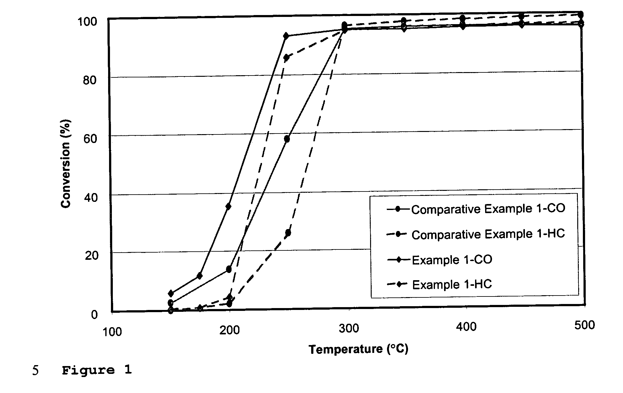
[0040] The resulting catalyst is tested on a laboratory reactor. The testing gas composition contains 800 ppm CO; 250 ppm C3H6, 250 ppm C3H8, ...
example 2
[0043] The alumina / zeolite / tin oxide washcoat slurry prepared in Example 1 is used for the coating of SiC foam. The SiC foam substrates are 4.66″ in diameter with a 1″ length, and porosities of 30 ppi, 40 ppi and 50 ppi. During the coating process, the foams are dipped into the slurry and extra slurry is removed by vacuum suction or centrifuging. The coated substrates are then dried at 125° C. for 2-3 hours and calcined at 550° C. for 3 hours. The washcoat loading is 40 g / L.
[0044] Pt deposition is then carried out by impregnation, as described in Example 1, followed by drying at 125° C. for 2-3 hours and calcination at 550° C. for 3 hours. The Pt loading is 0.88 g / L.
[0045] The foam substrates are stacked in a stainless steel housing with increasing pore density and placed into the exhaust flow of the LPA2 diesel engine for testing. This device is also called a flow through trap (FTT) since it has about 40-70% soot filtration efficiency. The LPA2 diesel engine has 2 cylinders and a...
example 3
[0048] The alumina / zeolite / tin oxide washcoat slurry prepared in Example 1 is used for the coating of a conventional cordierite wall flow filter of 4.66″ diameter by 6″ length from Corning. The slurry is diluted and washcoated to the filter substrate followed by drying and calcination at 500° C. for 2-6 hours. The washcoating loading is 40 g / l. A Pt solution (platinum sulfite acid) is then deposited on the coated filtered substrate followed by drying and calcination at 500° C. The Pt loading is 1.77 g / l.
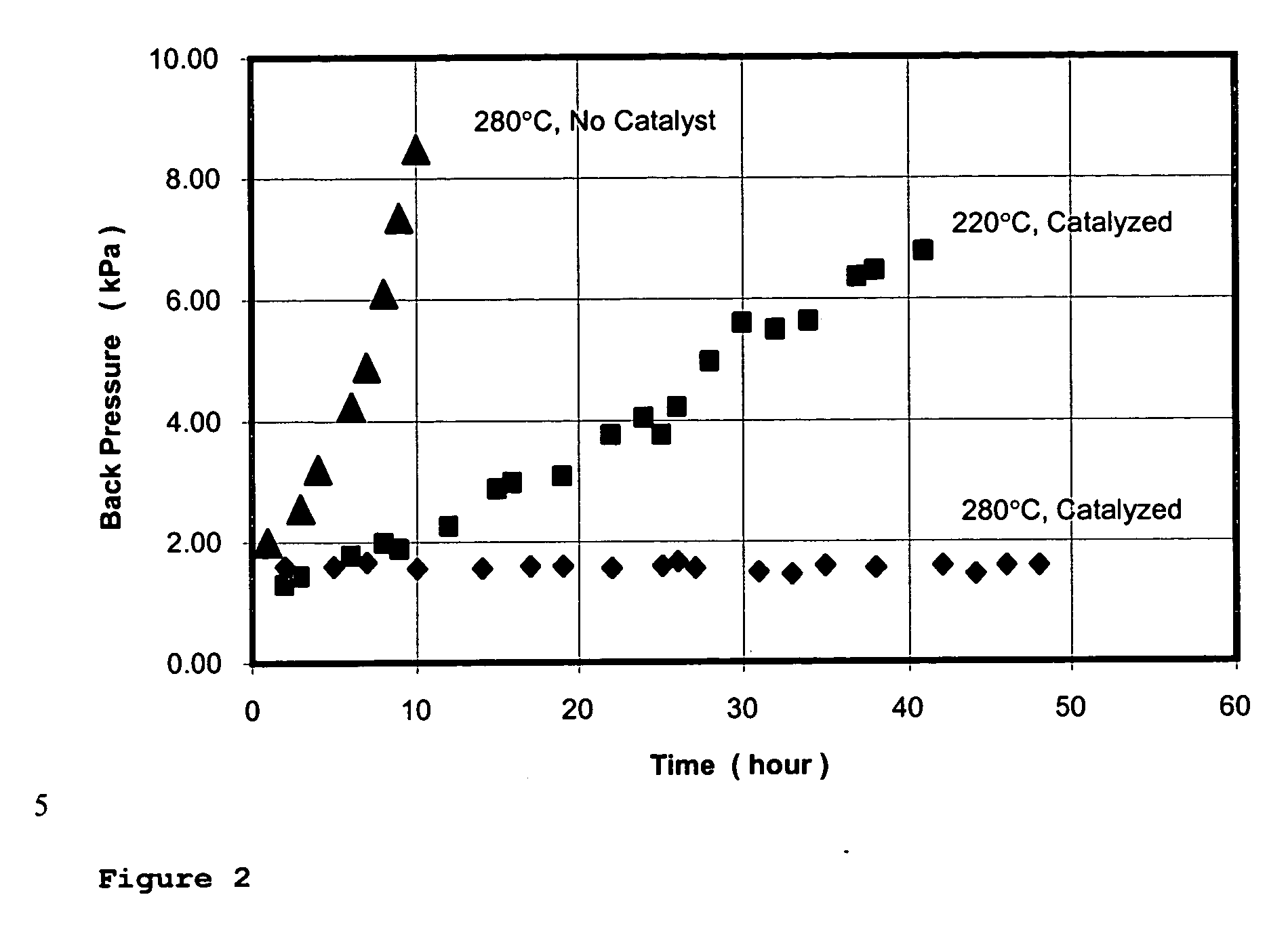
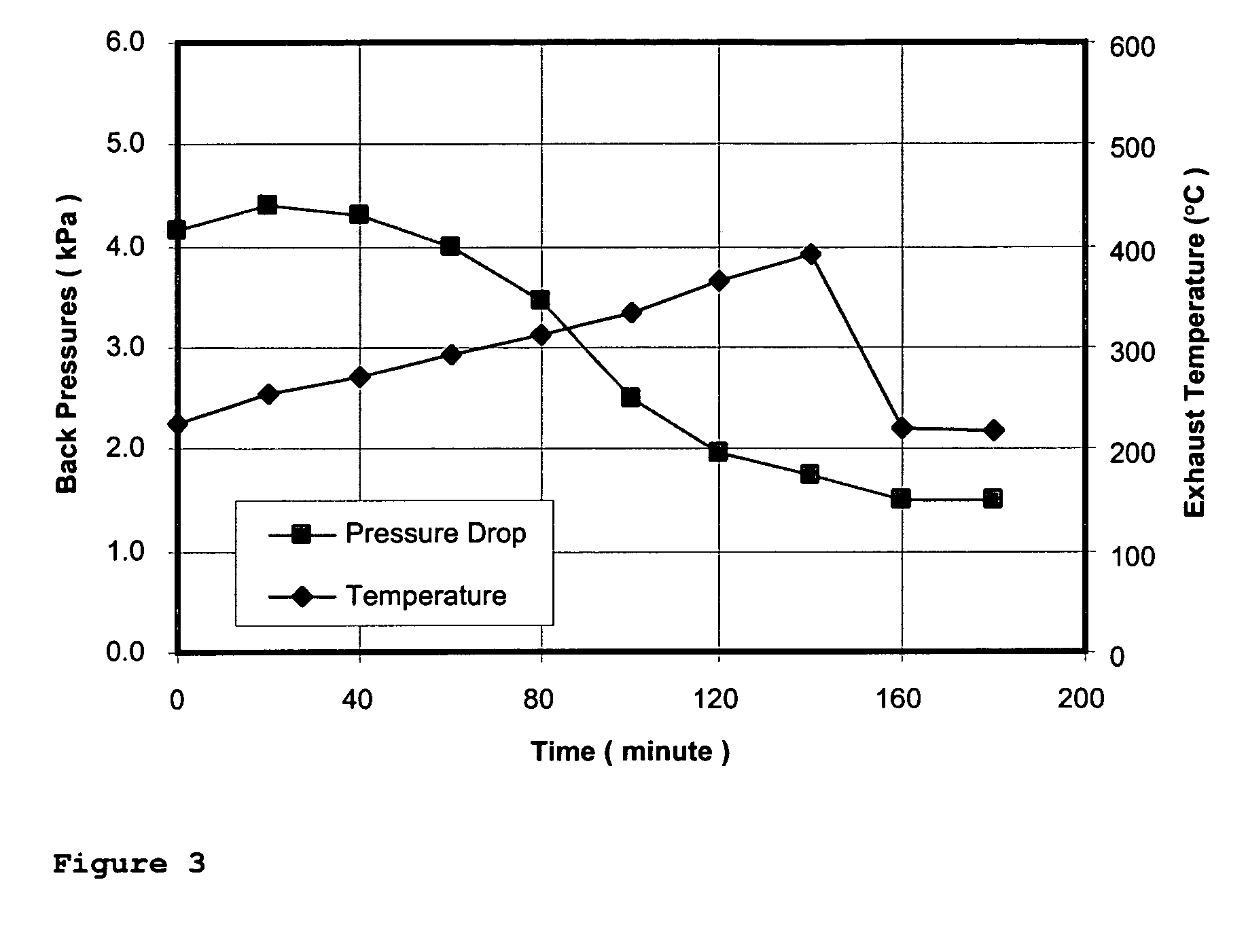
[0049] The catalyzed particulate filter is tested on the LPA2 diesel engine powered generator as described in Example 2. The device is first loaded with soot at low temperature. Then the exhaust temperature is increased gradually. The back pressure across the device is monitored. The back pressure across the device increases with time and then decreases at a certain point. The point where the back pressure starts to decrease is called the “balance point temperature.” As shown in FIG...
PUM
| Property | Measurement | Unit |
|---|---|---|
| temperature | aaaaa | aaaaa |
| particle size | aaaaa | aaaaa |
| size | aaaaa | aaaaa |
Abstract
Description
Claims
Application Information