
Optical fiber manufacture

Inactive Publication Date: 2006-09-28
ATKINS ROBERT M +3
View PDF9 Cites 7 Cited by
  • Summary
  • Abstract
  • Description
  • Claims
  • Application Information

AI Technical Summary

Benefits of technology

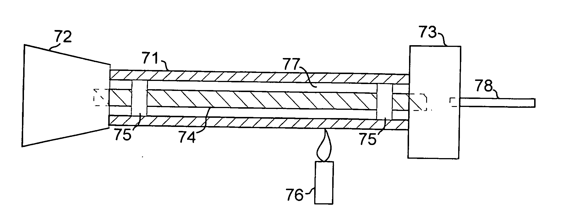
[0010] We have developed a technique that allows the use of MCVD for producing large preform core rods in a rod-in-tube process. High-quality glass is deposited on the inside of a MCVD starting tube, and the tube collapsed in the usual manner to form a solid rod. The starting tube, at this point the outside shell of the rod, is then removed from the solid rod leaving just MCVD-deposited material. The rod is then inserted

Problems solved by technology

However, limiting aspects in MCVD and similar inside deposition processes are the size and quality of the starting tube and the total amount of glass that can be deposited inside a starting tube.
The limitation on the total amount of deposited glass necessarily limits the number of distinct doped regions or segments of a given size that can be accommodated in a preform of this type.
As a general proposition, VAD methods are effective and widely practiced, but they still do not match the ability of MCVD to control precisely the radial deposition profile of index changing dopants such as germanium and fluorine.
Because of this, VAD methods and other soot deposition / subsequent sintering methods such as Outside Vapor Deposition (OVD) are limited in the complexity of the fiber designs that can be efficiently produced.
Making these very large cladding bodies with a soot based synthetic glass process leads to high quality glass but requires extensive processing and is relatively expensive.
Large bodies of fused quartz are less expensive but are generally not of sufficient purity for large preforms.
However, the MCVD starting tube can be a limiting factor in several ways.
The most direct limitation is when the glass in the MCVD starting tube is simply not of sufficient quality and low loss for large state of the art preforms (where some fraction of the optical power would be carried by the starting tube material).
If the initial tube quality limitation is avoided by the use of ultra pure (and typically expensive) material to fabricate the starting tube, the exposure of the tube to the oxy-hydrogen torch typically used in MCVD as a heat source can compromise the effective starting tube quality by the addition of hydroxyl ions to a significant depth.
Finally, the desired refractive index profile may require a dopant level in the region provided by the starting tube glass that is not compatible with successful MCVD processing (viscosity, tube stability or heat transfer considerations).
While the MCVD process is capable, along with the VAD and OVD processes, of producing very high quality glass, the MCVD glass is deposited inside a starting tube which, because of the reasons outlined above, can disadvantageously limit the application of the rod in tube method to preforms below a given size.

Method used


Image

  • Optical fiber manufacture
  • Optical fiber manufacture
  • Optical fiber manufacture

Examples


Embodiment Construction

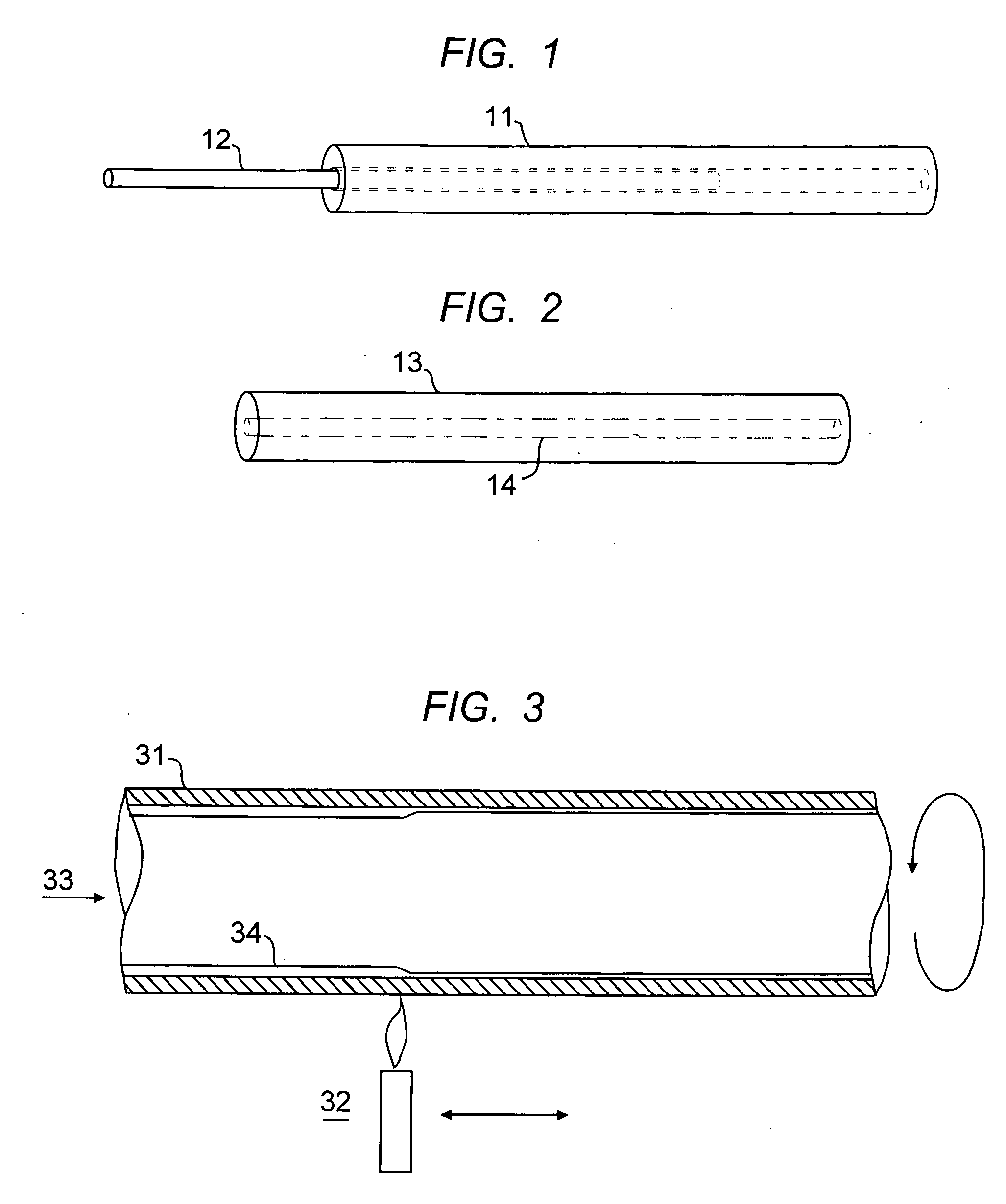
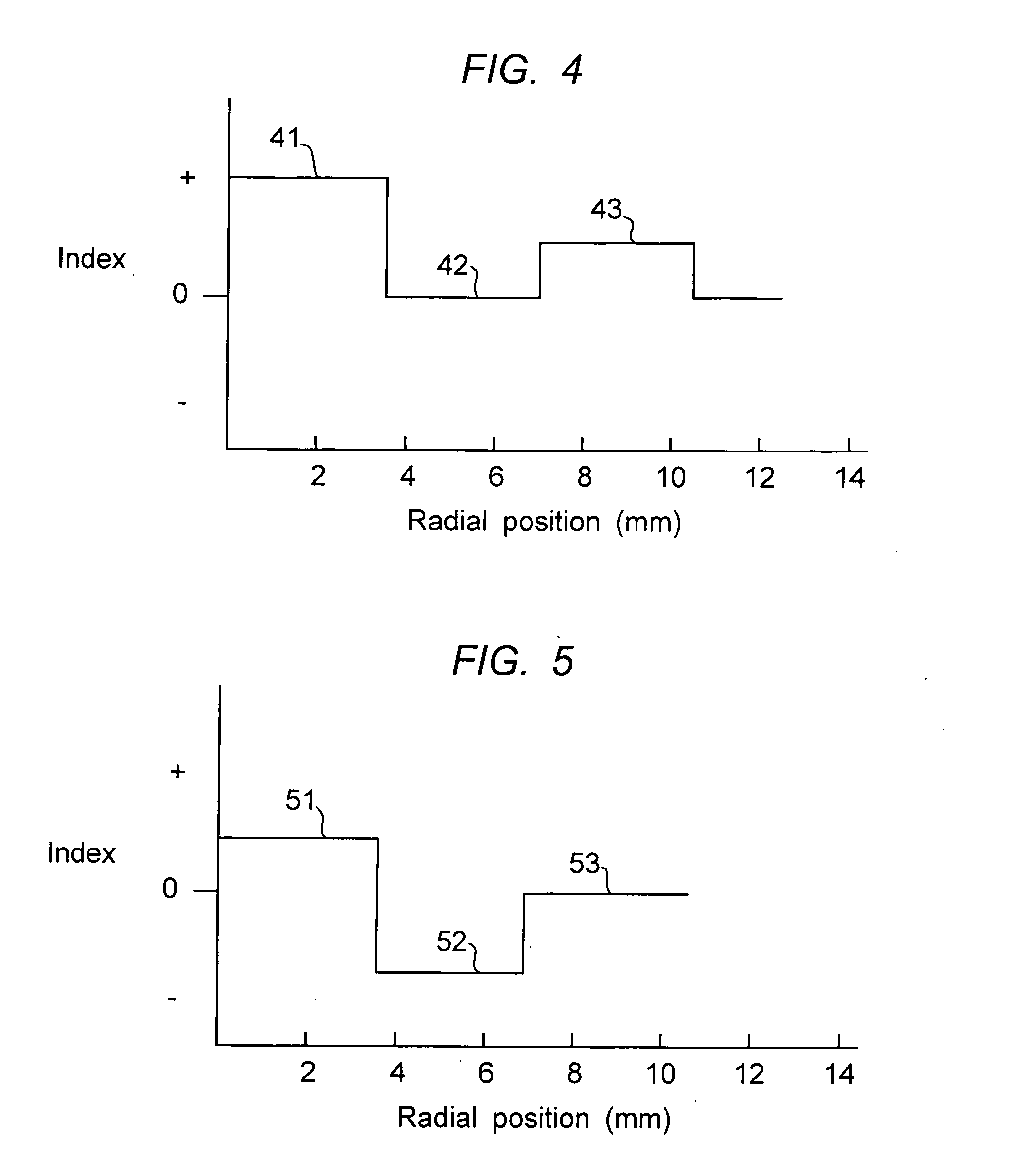
[0021] Typical rod-in-tube methods are described in conjunction with FIGS. 1 and 2. It should be understood that the figures referred to are not necessarily drawn to scale. A cladding tube representative of dimensions actually used commercially has a typical length to diameter ratio of 10-15. The core rod 12 is shown being inserted into the cladding tube 11. There exist several common options for the composition of the core rod, It may be pure silica, adapted to be inserted into a down-doped cladding tube. It may have a pure silica center region with a down-doped inner cladding region. It may have an up-doped, e.g. germania doped, core region surrounded by a pure silica cladding region. It may have an up-doped center core region surrounded by a down-doped inner cladding region. All of these options, and many variations and elaborations, are well known in the art and require no further exposition here. However, the preferred embodiment of the invention is aimed at the case where the ...


PUM

PropertyMeasurementUnit
Diameteraaaaaaaaaa
Sizeaaaaaaaaaa
Contentaaaaaaaaaa

Abstract

The specification describes methods for the manufacture of very large optical fiber preforms wherein the core material is produced by MCVD. Previous limitations on preform size inherent in having the MCVD starting tube as part of the preform process are eliminated by removing the MCVD starting tube material from the collapsed MCVD rod by etching or mechanical grinding. Doped overcladding tubes are used to provide the outer segments of the refractive index profile thus making most effective use of the MCVD produced glass and allowing the production of significantly larger MCVD preforms than previously possible.

Description

RELATED APPLICATION [0001] This application is a continuation of application Ser. No. 10 / 366,888, filed Feb. 14, 2003.FIELD OF THE INVENTION [0002] This invention relates to optical fiber manufacture, and more specifically to improved optical fiber preform fabrication techniques. BACKGROUND OF THE INVENTION [0003] Manufacture of optical fiber performs, the glass blanks from which optical fibers are drawn, typically involves a rotating lathe, where pure glass or glass soot is formed on a rotating member by chemical vapor deposition or a modification thereof. All successful methods of fiber manufacture should assure that the optical quality and purity of the preform glass is high. In particular, the glass making up the central portion or core of the preform should be of the highest purity since most of the optical power in the fiber will be carried within this region. A significant advance in this direction occurred with the introduction of the so-called Modified Chemical Vapor Deposi...

Claims


Application Information

Patent Timeline
IPC IPC(8): C03B37/028C03B37/018C03B37/012
CPCC03B37/01211C03B37/01248C03B37/01861C03B37/01869C03B2201/04C03B2203/22
Inventor ATKINS, ROBERT M.FLEMING, JAMES W.GLODIS, PAUL F.YAN, MAN F.
Owner ATKINS ROBERT M
Learn More