Dynamic optical reflector and interrogation system

Active Publication Date: 2006-09-28
QINETIQ LTD
View PDF10 Cites 32 Cited by
  • Summary
  • Abstract
  • Description
  • Claims
  • Application Information

AI Technical Summary

Benefits of technology

[0037] Advantageously, by taking the returns from both lasers into account, the signal-to-noise ratio of the signal received from the tag at the interrogato

Problems solved by technology

Specific tag designs vary, and each has associated limitations.
Furthermore, the wavelength of the light passed by such modulators varies as the angle of incidence deviates from the normal owing to the increase in optical path length within the device itself.
For these reasons at least, such devices are in general not suitable for use as general purpose identification tags, particularly in situations in which an interrogating light source and detector may be arbitrarily located relative to the light-receiving surface of the tag.
However, such techniques are unable to provide reliable communication links at data rates in excess of 50 kbps over a w

Method used


Image

  • Dynamic optical reflector and interrogation system
  • Dynamic optical reflector and interrogation system
  • Dynamic optical reflector and interrogation system

Examples


Embodiment Construction

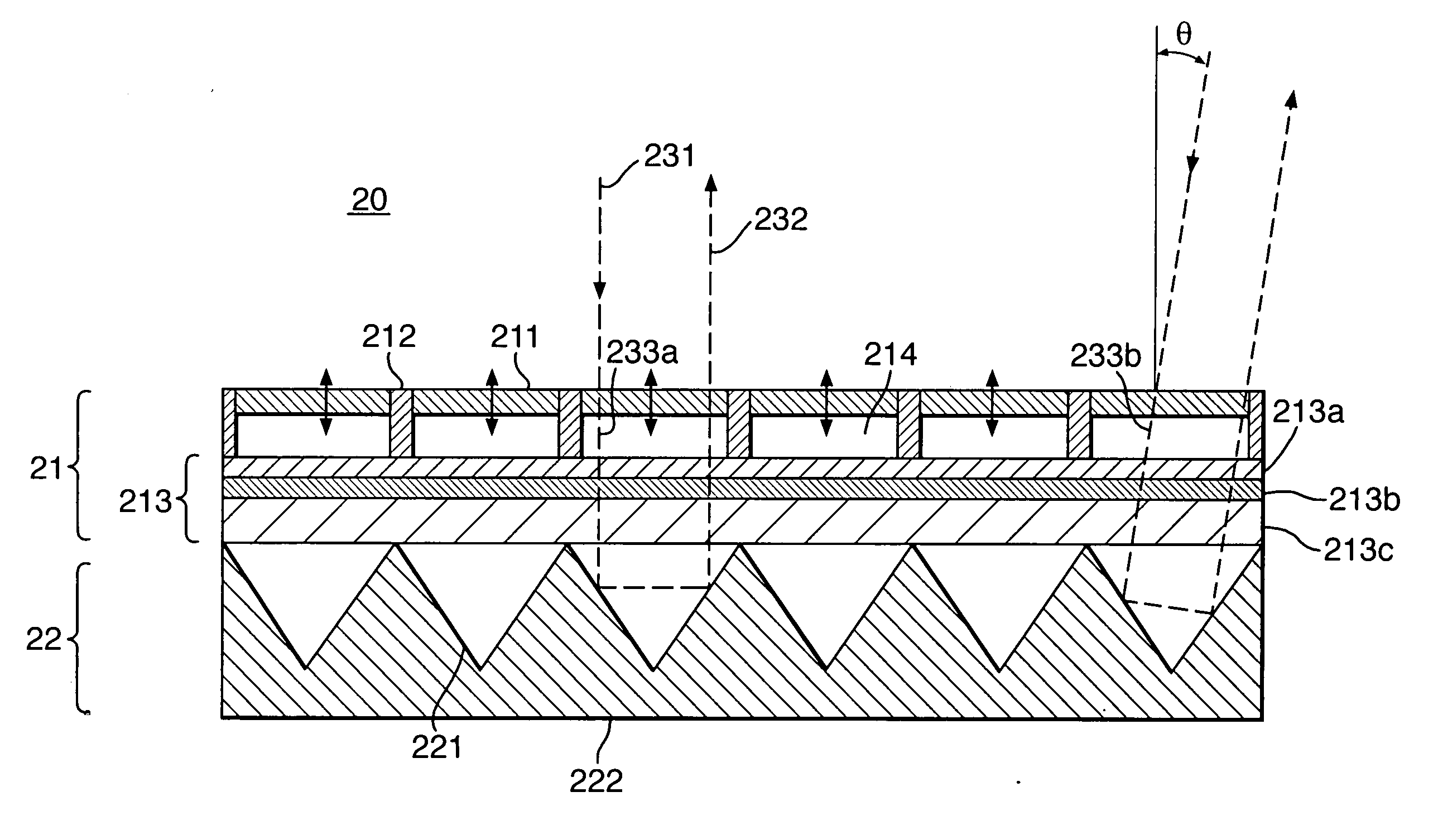
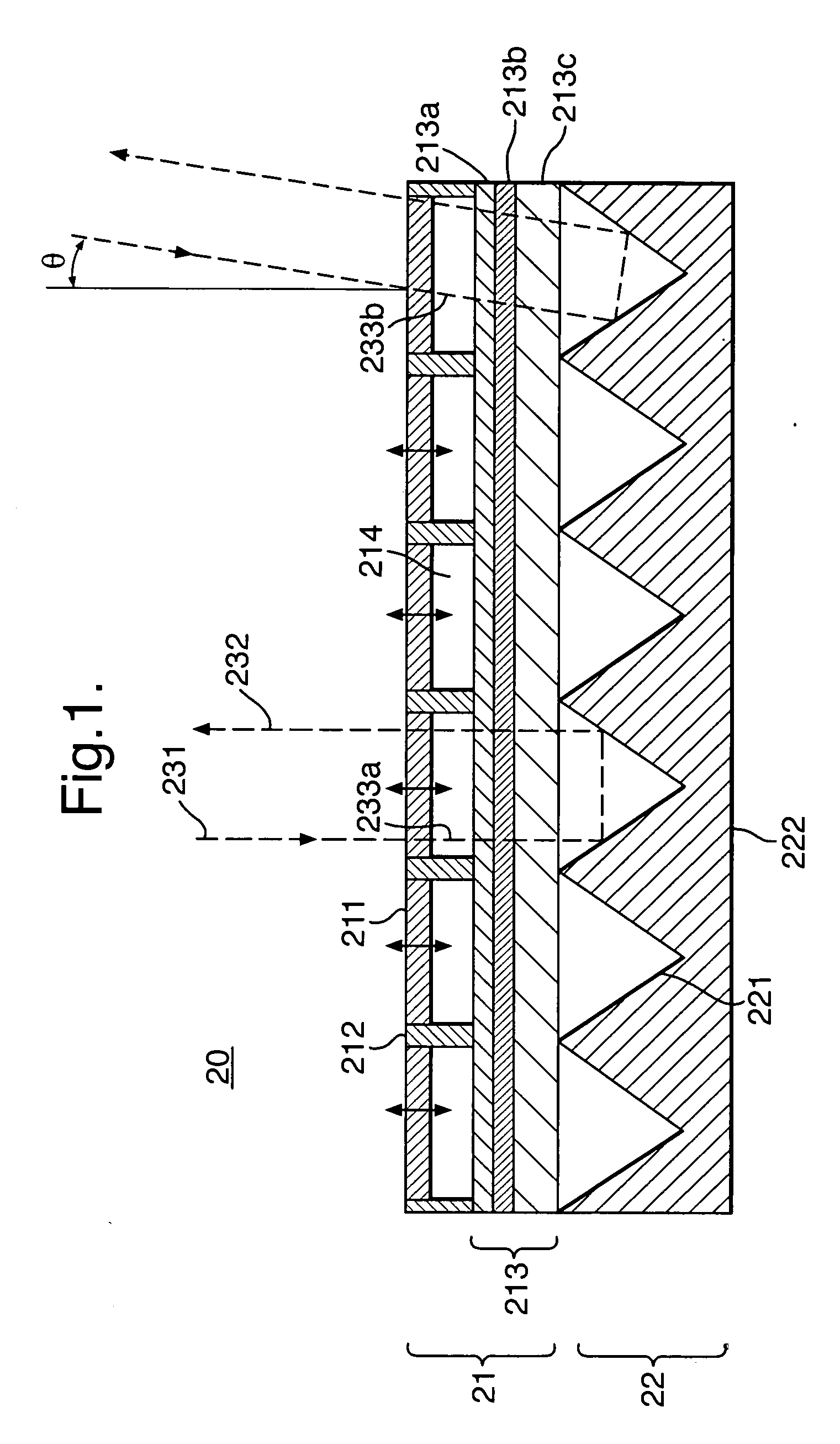
[0061] Referring to FIG. 1, the basis of the invention lies in an optical device 20 which combines an optical modulator 21 (for example a MOEMS modulator) with a retro-reflector 22 (for example a micro-corner cube array). The modulator may be a tuneable Fabry Perot etalon 21 which acts as a wavelength-selectable shutter, controlling the degree to which laser radiation 231 is admitted to the individual retro-reflecting elements 221.

[0062] The etalon comprises a composite membrane 211, a silicon wafer 213 (comprising multiple layers 213a-c), and electrostatically-driven elements 212 arranged to vary the separation between the membrane 211 and the wafer 213 which may comprise multiple layers 213a-c. Together these components define internal cavities 214 which may be air- or gas-filled cavities or, more preferably, vacuum cavities so as to avoid the damping effects of air / gas and to ensure acceptable phase shifts can be produced at high frequencies.

[0063] The membrane may itself compr...


PUM


Abstract

A retro-reflective identification tag capable of modulating an optical signal whereby to support bi-directional communication with an associated remote optical interrogation device. The tag comprises a MOEMS modulating layer over a retro-reflective substrate, giving the tag a wide angle of effective operation. The tag modulator may optionally be switched on only responsive to detection of a precursor beam from the interrogation system in order to save power. The interrogation device may make use of multiple optical wavelengths for communicating with the tag.

Description

FIELD OF THE INVENTION [0001] The present invention relates to apparatus, methods, signals, and other associated aspects relating to optical reflectors which can be remotely interrogated, along with systems incorporating the same. The present invention relates particularly to optical reflectors arranged to reflect, modulate, and filter incident light. BACKGROUND TO THE INVENTION [0002] It is known to provide dynamic optical tagging systems based on a number of different technologies. Such tags have a wide variety of applications including, for example, identification and / or tracking of vehicles (road tolling), equipment (cargo container tracking), or people and in access control systems (for example in employee identification badges used to control access to specific areas). Such applications include both military and civilian use. [0003] Known tagging systems have in common the basic concept of utilising a compact optically reflective tag which may be affixed, for example, to a veh...

Claims


Application Information

Patent Timeline
IPC IPC(8): G01C3/08G01S17/74G02B5/124
CPCG01S17/74G02B5/124G02B26/02G02B26/0841G02B26/08G02F1/21
Inventor SCOTT, ANDREW M.LEWIS, KEITH L.MCNIE, MARK E.BRUNSON, KEVIN M.JACKSON, DAVID J.RIDLEY, KEVIN D.
Owner QINETIQ LTD
Why Eureka
Try Eureka