Specific phase position detection circuit and method of the same
a phase position detection and phase position technology, applied in the direction of amplitude demodulation, process and machine control, instruments, etc., can solve the problems of failure to apply the required voltage to the discharge lamp, difficulty in identifying peak positions, and difficulty in retaining the discharge lamp. achieve the effect of high accuracy and stably keeping
- Summary
- Abstract
- Description
- Claims
- Application Information
AI Technical Summary
Benefits of technology
Problems solved by technology
Method used
Image
Examples
embodiment
A. Embodiment
A1. System Configuration
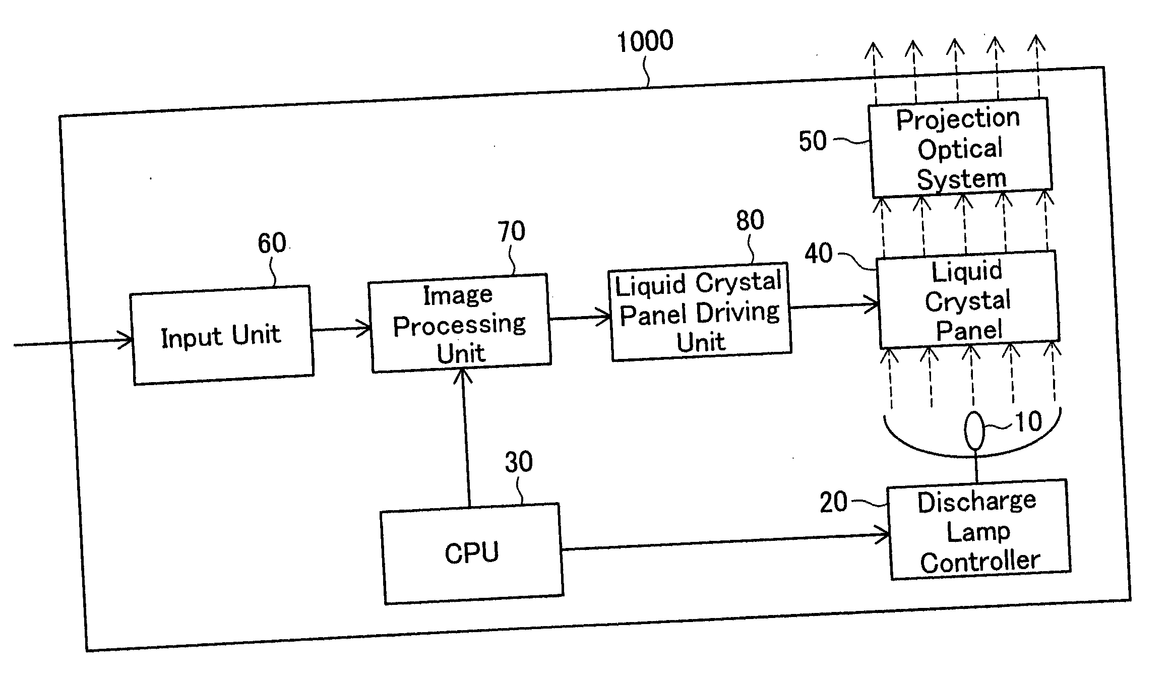
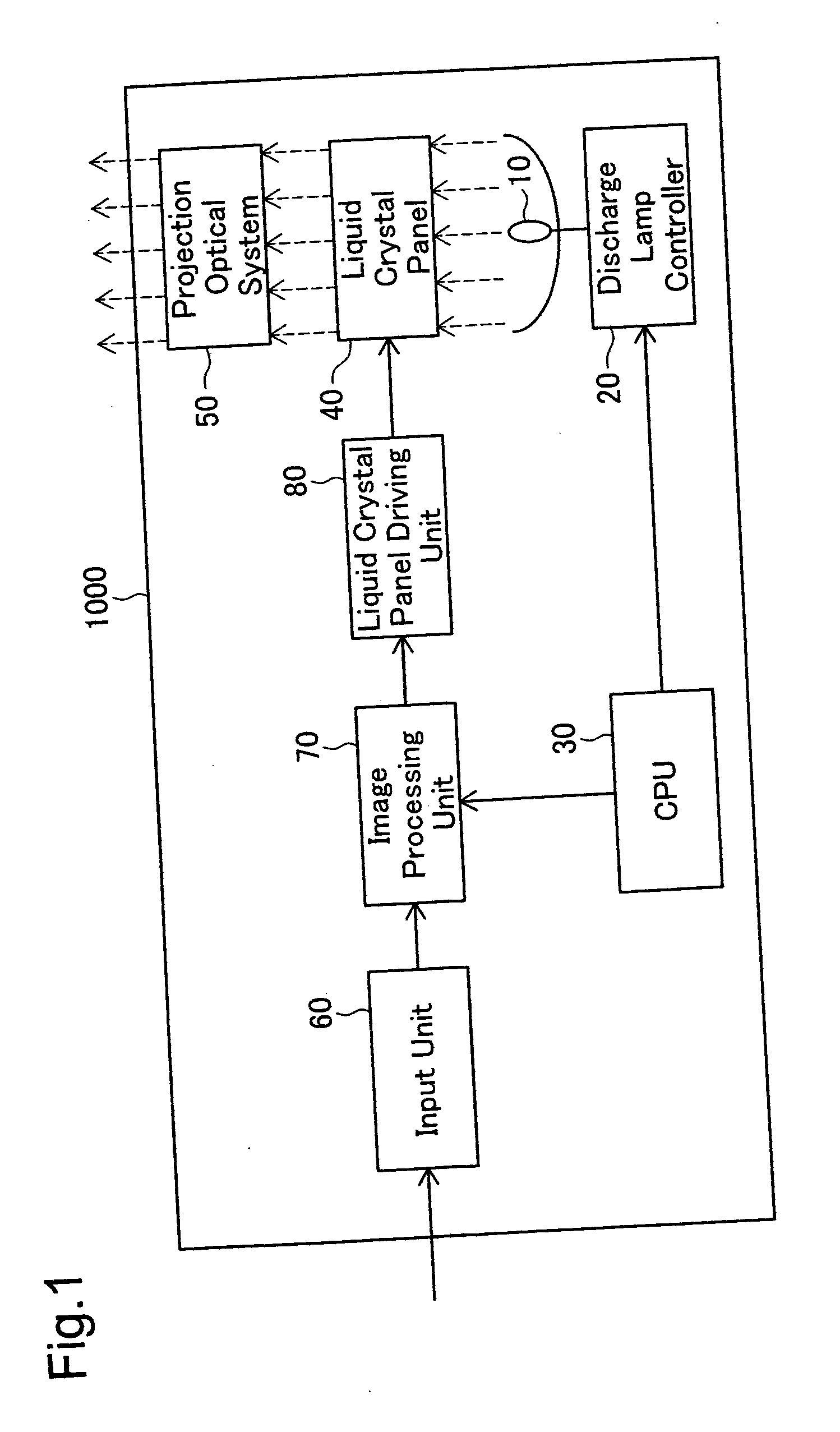
[0056]FIG. 1 schematically illustrates the configuration of a liquid crystal projector 1000 in one embodiment of the invention.
[0057] As illustrated in FIG. 1, the liquid crystal projector 1000 mainly has a discharge lamp 10, a discharge lamp controller 20 that controls lighting of the discharge lamp 10, a CPU 30, a liquid crystal panel 40, a projection optical system 50 including a projection lens, an input unit 60 that receives external analog signals, an image processing unit 70, and a liquid crystal panel driving unit 80 that drives the liquid crystal panel 40.
[0058] The input unit 60 receives analog video signals output from, for example, a video player, a TV set, or a personal computer, and converts the input analog video signals into digital video signals. The image processing unit 70 adjusts the input digital video signals to attain desired image display conditions (including contrast and sharpness) according to an instruction given b...
modified example 1
B1. MODIFIED EXAMPLE 1
[0117] In the liquid crystal projector 1000 of the embodiment described above, the voltage corresponding to the sinusoidal signal A1 is applied to the resonant unit 150. The source signal of the applied voltage may not be a sinusoidal wave but may have another waveform. Operation values may be determined corresponding to the respective waveforms and stored in the operation value storage element 340 (see FIG. 3).
[0118]FIG. 7 shows the waveforms of source signals and applied voltage signals and operation values set for the respective waveforms in Modified Example 1.
[0119] A sawtooth wave 1 of FIG. 7 has a peak position shifted by ‘0.8’ from a start position of each cycle that is assumed to be ‘1’. Setting an operation value of ‘0.7’ enables specification of a phase detection point relatively close to the peak position.
[0120] A sawtooth wave 2 has a peak position shifted by ‘0.2’ from a start position of each cycle. A triangular wave and a sinusoidal wave respe...
modified example 2
B2. MODIFIED EXAMPLE 2
[0122] The procedure of the embodiment sets the phase detection point of each cycle to the position shifted by ‘0.1’ from the center position of each high-level period of the comparison signal S110 assumed to be ‘1’. The phase detection point is, however, not restricted to the position shifted by ‘0.1’ from the center position. A closer position to the peak position, for example, a position shifted by ‘0.05’ from the center position, may be specified as the phase detection point.
[0123] In this modification, the phase detection point corresponds to the position of 10% before the center position in the specific time length between the start position and the center position in each high-level period of the comparison signal S110. According to the calculation similar to Equation (1) given above, the phase detection point is set at the position of 45% from the rising position in each high-level period of the comparison signal S110, which is assumed to be 100%. The ...
PUM
 Abstract
Description
Claims
Application Information
 - R&D
- Intellectual Property
- Life Sciences
- Materials
- Tech Scout
- Unparalleled Data Quality
- Higher Quality Content
- 60% Fewer Hallucinations
Browse by: Latest US Patents, China's latest patents, Technical Efficacy Thesaurus, Application Domain, Technology Topic, Popular Technical Reports.
© 2025 PatSnap. All rights reserved.Legal|Privacy policy|Modern Slavery Act Transparency Statement|Sitemap|About US| Contact US: help@patsnap.com


