
Heart state monitor method

Inactive Publication Date: 2006-09-28
CHANG KUO YUAN
View PDF4 Cites 4 Cited by
  • Summary
  • Abstract
  • Description
  • Claims
  • Application Information

AI Technical Summary

Benefits of technology

[0008] One object of the present invention is to propose a heart state monitor method. Different from recording the electric voltage in the heart, the heart state moinitor device provided by the present invention measures pressure signals reflected from a heart by imposing one or more pressure values on one's arm, wrist, finger or ankle to accurately know the heart status of the life body after numerical processing. Instead of the adjustment of ECG by professional people, the life body may be easily measured by a man or woman and the information for the health state of his or her heart may be easily read out.
[0009] Another object of the present invention is to propose a heart state monitor method, which can transmit the measured pressure signal of a life body to a medical center via a transmission circuit, and can record and analyze the current heart state of the life body in real time. The current heart state of the life body can thus be easily measured and accurately recorded at any place so that the life body and medical staffs can grasp the current heart state of the life body and thereby make real-time and effective treatment.

Problems solved by technology

In addition to age, high blood fat, high cholesterol in the blood, hypertension, diabetes and heredity, people having a too high content of fat due to smoking, lack of exercise, fatness and abnormal diet may easily catch cardiovascular diseases.
However, either exercise electrocardiogram or the all-day electrocardiogram is very cumbersome for the patient.
Moreover, because the cardiovascular diseases do not occur all the time, it is sometimes difficult to find them.
This is very inconvenient for the patient, especially for a female patient.
Moreover, the measured result of a conventional heart measurement apparatus can only be analyzed by medical staffs.
Once the body of a patient has a bad status when he / she goes out for work or play, because the medical staffs cannot grasp the physiologic status of the patient immediately, it is usually too late for the patient to take medical treatment.

Method used


Image

  • Heart state monitor method
  • Heart state monitor method
  • Heart state monitor method

Examples


Embodiment Construction

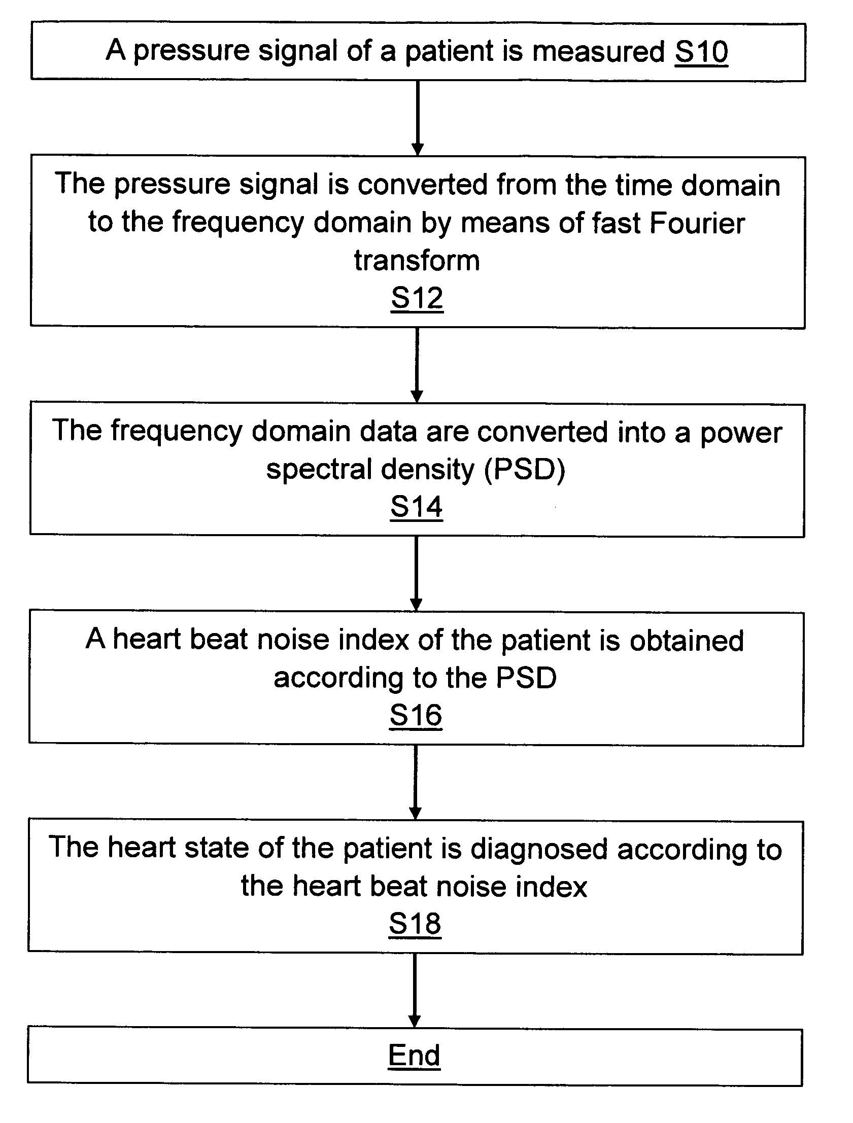
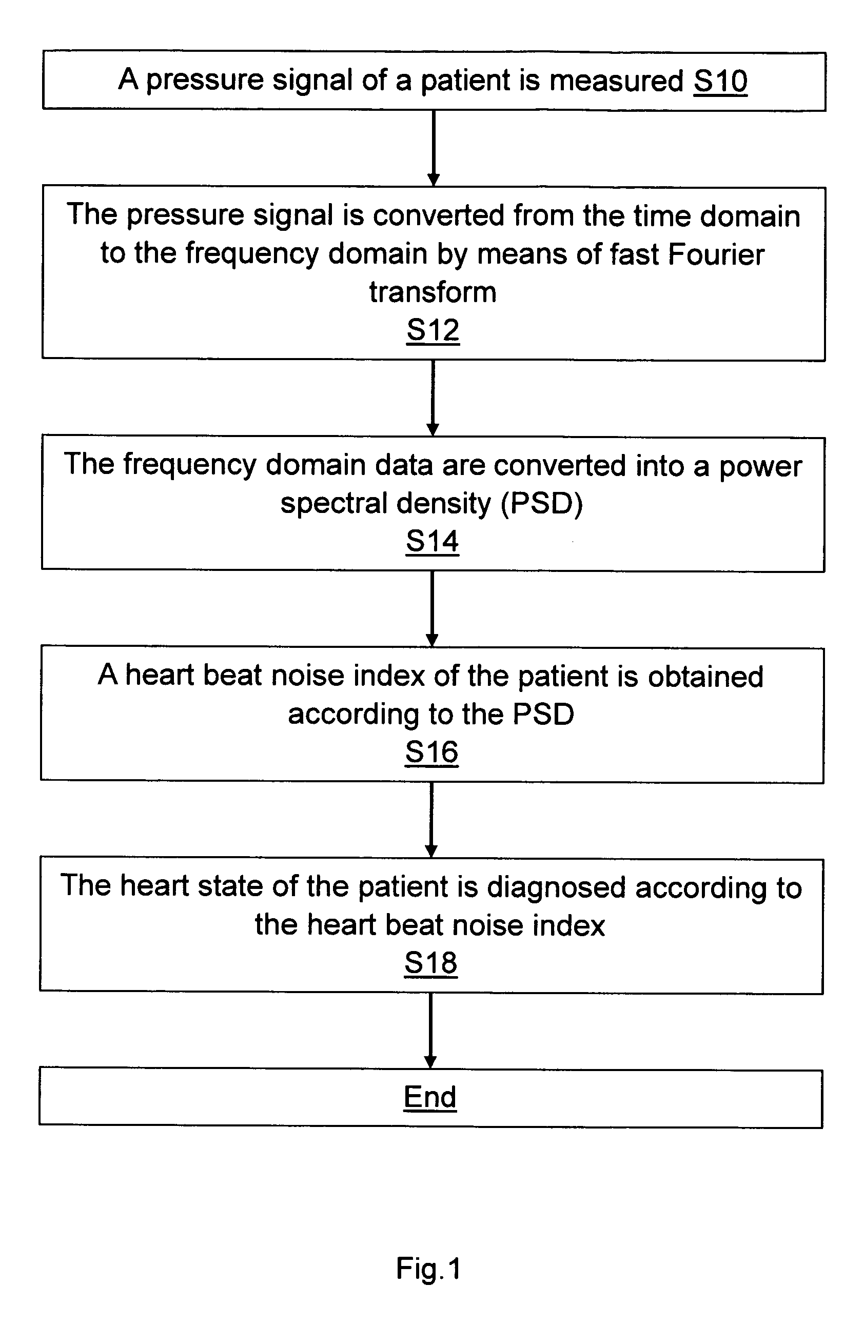
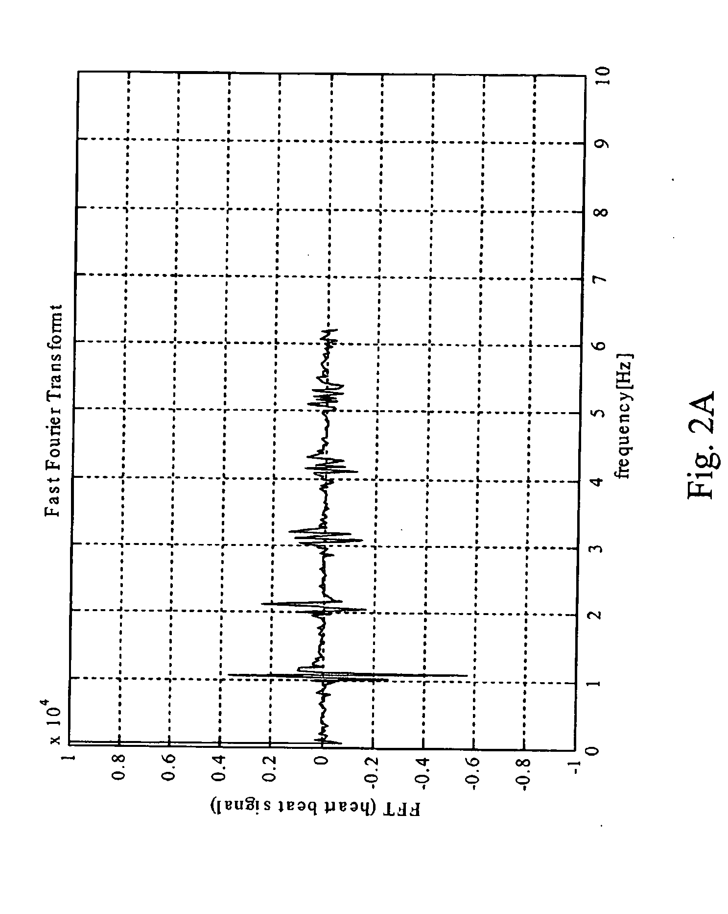
[0023] As shown in FIG. 1, a heart state monitor method of the present invention comprises the following steps. First, pressure is imposed on the arm of a patient for measurement to obtain a pressure signal that represents blood injected into a main artery by heart (Step S10). The pressure signal is then transmitted to a medical center via a transmission circuit. The medical center transforms the received pressure signal from the time domain to the frequency domain by means of Fourier transform, and then integrates and stores these data into a database (Step S12). The frequency domain data are then converted into a power spectral density (PSD) (Step S14). Next, a heart beat noise index of the patient is calculated out according to many noise waveforms between harmonics in the PSD (Step S16). Finally, the heart state of the patient is diagnosed according to the heart beat noise index (Step S18).

[0024] Accordingly, the pressure signal is acquired by imposing pressure or pressures on ...


PUM


Abstract

A heart state monitor method is proposed. The pressure signal of a life body is measured and then performed by Fourier transform analysis. Next, the frequency domain data of the pressure signal are converted into a power spectral density (PSD). A heart beat noise index of the life body is then obtained according to the PSD. Finally, the heart state of the life body is diagnosed according to the heart beat noise index. The heart beat noise index may be quickly discriminated to let the life body and medical staffs grasp the current heart state of the life body at any time.

Description

[0001] This is a continuation-in-part of application Ser. No. 10 / 345,485, filed Jan. 17, 2003.BACKGROUND OF THE INVENTION [0002] 1. Field of the Invention [0003] The present invention relates to a heart state monitor method and, more particularly, to a monitor method capable of quickly and easily measuring and grasping the heart state of a life body at any time. [0004] 2. Background of the Related Art [0005] Cardiovascular diseases are one of the primary pathogenic factors of people all the time. In addition to age, high blood fat, high cholesterol in the blood, hypertension, diabetes and heredity, people having a too high content of fat due to smoking, lack of exercise, fatness and abnormal diet may easily catch cardiovascular diseases. Cardiovascular diseases are basically measured by apparatuses. In the prior art, an electrocardiogram (ECG, EKG) of a heart is measured by an apparatus to determine which situation a patient suffers from. The electrocardiogram (ECG or EKG) is a noni...

Claims


Application Information

Patent Timeline
IPC IPC(8): A61B5/02A61B5/00A61B5/0402G16Z99/00
CPCA61B5/0002A61B5/0402A61B5/7257A61B5/7203A61B5/7232A61B5/7239A61B5/022A61B5/0245A61B5/4836A61B5/7242G16H40/63G16H50/50G16H50/20A61B5/316A61B5/318G16Z99/00
Inventor CHANG, KUO-YUAN
Owner CHANG KUO YUAN
Learn More