Noise suppressor

a noise suppressor and noise technology, applied in the direction of overvoltage protection resistors, emergency protective arrangements for limiting excess voltage/current, conversion with intermediate conversion to dc, etc., can solve the problem of difficult to move the self-resonant point to a higher frequency side, adversely affecting high-pass performance at a self-resonant frequency or higher, and affecting the attenuation characteristic of parasitic components. , to achieve the effect of preventing the degradation of parasi

Inactive Publication Date: 2006-10-05
TDK CORPARATION
View PDF2 Cites 17 Cited by
  • Summary
  • Abstract
  • Description
  • Claims
  • Application Information

AI Technical Summary

Benefits of technology

[0047] Thereby, while magnetic coupling between the first and the third winding wires and the second winding wire is kept strong, the inductance of the whole second winding wire can be easily reduced. For example, when the magnetic permeability μ1 of the first core and the magnetic permeability μ2 of the second core are set so as to satisfy an appropriate condition, the inductance of the whole second winding wire can be easily reduced to be smaller than the inductance per turn in the first winding wire and the inductance per turn in the third winding wire.
[0048] In the noise suppressor according to the first embodiment of the invention, the second winding wire is magnetically coupled to the first winding wire disposed on the first current-carrying wire, and the inductance of the second winding wire and the resonant frequency of a predetermined circuit portion are set to satisfy an appropriate condition, so even if the parasitic capacitor is formed in the first winding wire on the current-carrying wire, thereby a self-resonant point is produced, the self-resonant point can be moved to a higher frequency side, and the influence of the parasitic capacitor can be equivalently reduced. Thereby, degradation in the attenuation characteristic by a parasitic component can be prevented so as to obtain a favorable attenuation characteristic.
[0049] In the noise suppressor according to the second embodiment of the invention, the second winding wire is magnetically coupled to the first winding wire disposed on the first current-carrying wire through the use of two cores equivalently, and the inductance of the second winding wire and the resonant frequency of a predetermined circuit portion are set to satisfy an appropriate condition, so even if a parasitic capacitor is formed in the first winding wire on the current-carrying wire, thereby a self-resonant point is produced, the self-resonant point can be moved to a higher frequency side, and the influence of the parasitic capacitor can be equivalently reduced. Thereby, degradation in the attenuation characteristic by a parasitic component can be prevented so as to obtain a favorable attenuation characteristic.
[0050] In the noise suppressor according to the third embodiment of the invention, the second winding wire is magnetically coupled to the first winding wire disposed on the first current-carrying wire, and the fourth winding wire is magnetically coupled to the third winding wire disposed on the second current-carrying wire, and the inductance of the second winding wire, the inductance of the fourth winding wire and the resonant frequency of a predetermined circuit portion are set to satisfy appropriate conditions, so even if a parasitic capacitor is formed in the first and the third winding wires on the current-carrying wires, thereby a self-resonant point is produced, the self-resonant point can be moved to a higher frequency side, and the influence of the parasitic capacitor can be equivalently reduced. Thereby, degradation in the attenuation characteristic by a parasitic component can be prevented so as to obtain a favorable attenuation characteristic.
[0051] In the noise suppressor according to the fourth embodiment of the invention, the second winding wire is magnetically coupled to the first winding wire disposed on the first current-carrying wire and the third winding wire disposed on the second current-carrying wire through the use of two cores equivalently, and the inductance of the second winding wire and the resonant frequency of a predetermined circuit portion are set to satisfy appropriate conditions, so even if a parasitic capacitor is formed in the first and the third winding wires on the current-carrying wires, thereby a self-resonant point is produced, the self-resonant point can be moved to a higher frequency side, and the influence of the parasitic capacitor can be equivalently reduced. Thereby, degradation in the attenuation characteristic by a parasitic component can be prevented so as to obtain a favorable attenuation characteristic.

Problems solved by technology

Therefore, high-pass performance is not improved in a band equal to or higher than the self-resonant point, so it is difficult to obtain desired characteristics.
In other words, the typical LC filter has a self-resonant point at a low frequency, so it adversely affects high-pass performance at a self-resonant frequency or higher.
Moreover, there are a number of trade-off limits such as needing to increase a space between windings or a space between a core and a line material in order to maintain a predetermined state for the purpose of increasing the number of turns or improving the frequency characteristics, so there is an issue that it is difficult to move the self-resonant point to a higher frequency side while securing the same inductance value.
For example, in reality, it is very difficult to move the self-resonant point to the side of approximately twice as high frequency.

Method used


Image

  • Noise suppressor
  • Noise suppressor
  • Noise suppressor

Examples


first embodiment

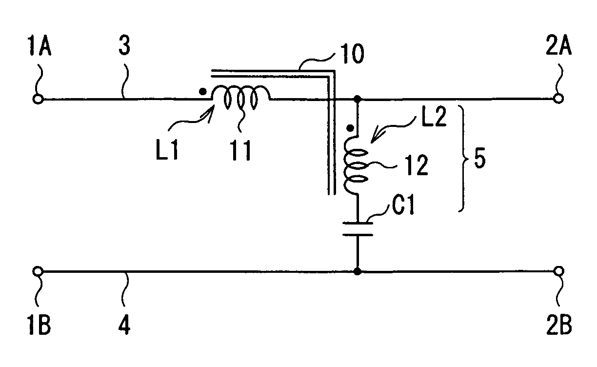
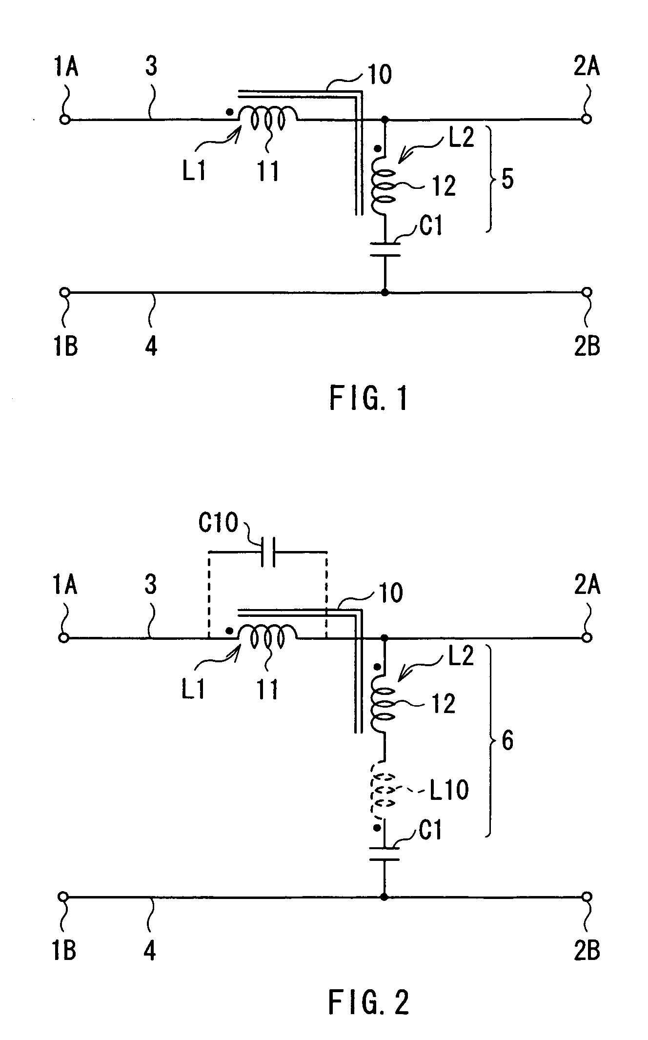
[0077] First, a noise suppressor according to a first embodiment of the invention will be described below. FIG. 1 shows an example of the noise suppressor according to the embodiment. The noise suppressor relates to a circuit for normal mode noise prevention.

[0078] The noise suppressor includes a pair of terminals 1A and 1B, another pair of terminals 2A and 2B, a first current-carrying wire 3 which establishes connection between the terminals 1A and 2A, and a second current-carrying wire 4 which establishes connection between the terminals 1B and 2B. The noise suppressor further includes a first winding wire 11 disposed on the first current-carrying wire 3, and a series circuit 5 having one end connected to the first current-carrying wire 3 and the other end connected to the second current-carrying wire 4. The series circuit 5 includes a capacitor C1 and a second winding wire 12 which are connected to each other in series. One end of the second winding wire 12 is connected to the f...

second embodiment

[0101] Next, a noise suppressor according to a second embodiment of the invention will be described below.

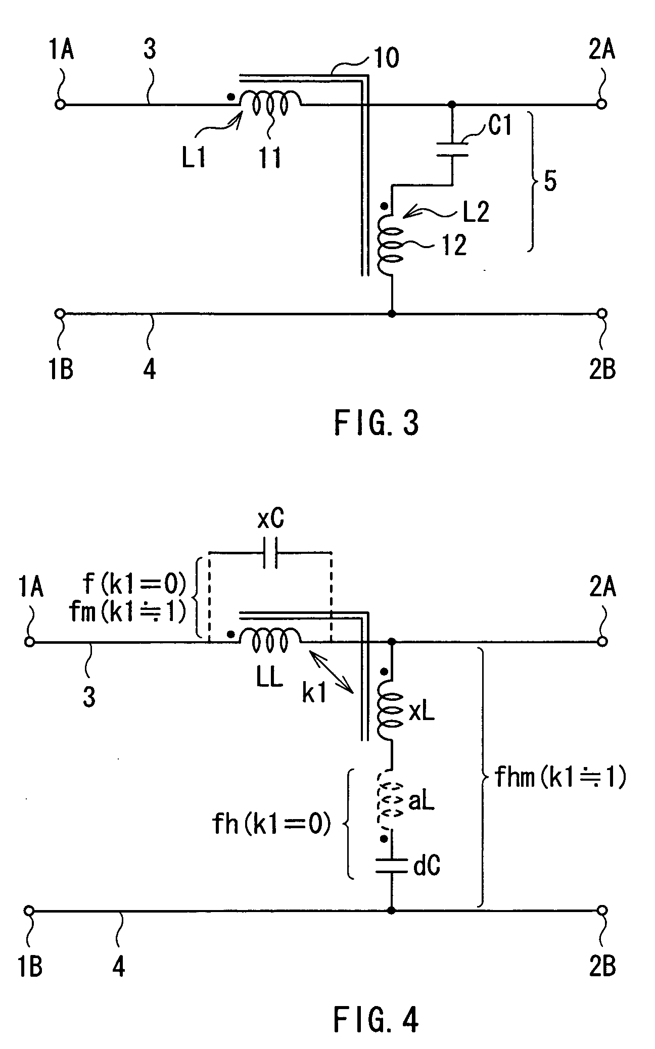
[0102] In the noise suppressor according to the above-described first embodiment, as one condition, the inductance xL of the whole second winding wire 12 is equal to or smaller than the inductance LL1 per turn in the first winding wire 11. Moreover, magnetic coupling between the first winding wire 11 and the second winding wire 12 is preferably strong (ideally, the coupling coefficient k1≈1). However, in the case of the structure in which the first winding wire 11 and the second winding wire 12 are magnetically coupled directly to each other via the common core 10, it is difficult to satisfy the condition of xL≦LL1, and for the inductance xL to be smaller than the inductance LL1 per turn while magnetic coupling between the first winding wire 11 and the second winding wire 12 is kept strong.

[0103] For example, as shown in FIG. 10, when the second winding wire 12 is wound so tha...

third embodiment

[0112] Next, a noise suppressor according to a third embodiment of the invention will be described below.

[0113]FIG. 14 shows an example of the noise suppressor according to the embodiment. The embodiment relates to a circuit for common mode noise prevention. In the embodiment, like components are denoted by like numerals as of the noise suppressor according to the first and the second embodiments and will not be further described.

[0114] The noise suppressor includes the first winding wire 11 disposed on the first current-carrying-wire 3 and a first series circuit 5-1 having one end connected to the first current-carrying wire 3 and the other end connected to ground. The first series circuit 5-1 includes the first capacitor C1 and the second winding wire 12 which are connected to each other in series. One end of the second winding wire 12 is connected to the first current-carrying wire 3, and the other end of the second winding wire 12 is connected to one end of the first capacitor...


PUM


Abstract

A noise suppressor capable of preventing degradation in an attenuation characteristic by a parasitic component so as to obtain a favorable attenuation characteristic is provided. The noise suppressor includes a first winding wire disposed on a first current-carrying wire and a series circuit including a capacitor and a second winding wire which are connected to each other in series. The first winding wire and the second winding wire are magnetically coupled to each other. The inductance xL of the whole second winding wire is smaller than the inductance LL of the whole first winding wire (xL<LL). Moreover, it is desirable that the inductance xL of the whole second winding wire is equal to or smaller than the inductance LL1 per turn in the first winding wire (xL≦LL1).

Description

BACKGROUND OF THE INVENTION [0001] 1. Field of the Invention [0002] The present invention relates to a noise suppressor which suppresses noise transmitted through a first current-carrying wire and a second current-carrying wire. [0003] 2. Description of the Related Art [0004] Power electronics devices such as switching power supplies, inverters, lighting circuits for lighting fixtures include a power converter circuit which converts power. The power converter circuit includes a switching circuit which converts a direct current into an alternating current with a rectangular wave. Therefore, the power converter circuit produces a ripple voltage with a frequency equivalent to the switching frequency of the switching circuit or noise associated with the switching operation of the switching circuit. The ripple voltage or noise adversely affects other devices. Therefore, it is necessary to arrange a means for reducing the ripple voltage or noise between the power converter circuit and the...

Claims


Application Information

Patent Timeline
Patent Type & Authority Applications(United States)
IPC IPC(8): H01Q1/00
CPCH02M1/44H03H7/09H03H7/1725H03H7/427H03H7/1758H02M1/12
Inventor SAITOH, YOSHIHIRO
Owner TDK CORPARATION
Why Eureka
Try Eureka