Method and apparatus for localized infrared spectrocopy and micro-tomography using a combination of thermal expansion and temperature change measurements

a technology applied in the field of localized infrared spectrocopy and microtomography using a combination of thermal expansion and temperature change measurement, can solve the problems of not being able to achieve high spatial resolution, not being able to teach or suggest multi-dimensional image using multiplicity of modulations at different frequencies

Inactive Publication Date: 2006-10-05
ANASYS INSTR
View PDF12 Cites 27 Cited by
  • Summary
  • Abstract
  • Description
  • Claims
  • Application Information

AI Technical Summary

Benefits of technology

[0032] Another object of the present invention is to provide a resistive thermal probe which serves as a point source of heat (in addition to sensing temperature and performing the functions listed in the objects above), such that it can produce the high-frequency temperature modulation that is needed for the user to choose the volume of material being spectroscopically analyzed at each individual location selected.

Problems solved by technology

Methods originally employed suffered from the limitations imposed by the finite optical wavelengths of the detection systems used.
As a result, these methods have not been able to accomplish high spatial resolution.
Hammiche 2004, however, does not teach or suggest creating a multidimensional image using multiplicity of modulations at different frequencies.
While Claybourn teaches sub-surface thermal imaging using an infra red source, Claybourn does not teach or suggest chemical multidimensional tomography.
The limitation of photoacoustic spectroscopy (PAS) is that it measures the response of the whole surface, it does not provide images and thus no publications on this method teach how tomographic reconstruction of a 3D image can be achieved.
As discussed above, the limitation of PAS is that it is not spatially resolved in the x and y planes.
Furthermore, in the general case where a complex or unknown sample is being studied, the data on the thermal properties of the materials being used is lacking, meaning that calculations of actual depths penetrated are approximate at best.
No successful tomography with experimental data was achieved.
However, the teachings of Smallwood et al. and Hammiche '425 are limited to providing images of thermal properties.
However, this literature does not teach or suggest how detailed accurate tomographic images can be obtained.

Method used


Image

  • Method and apparatus for localized infrared spectrocopy and micro-tomography using a combination of thermal expansion and temperature change measurements
  • Method and apparatus for localized infrared spectrocopy and micro-tomography using a combination of thermal expansion and temperature change measurements
  • Method and apparatus for localized infrared spectrocopy and micro-tomography using a combination of thermal expansion and temperature change measurements

Examples


example 1

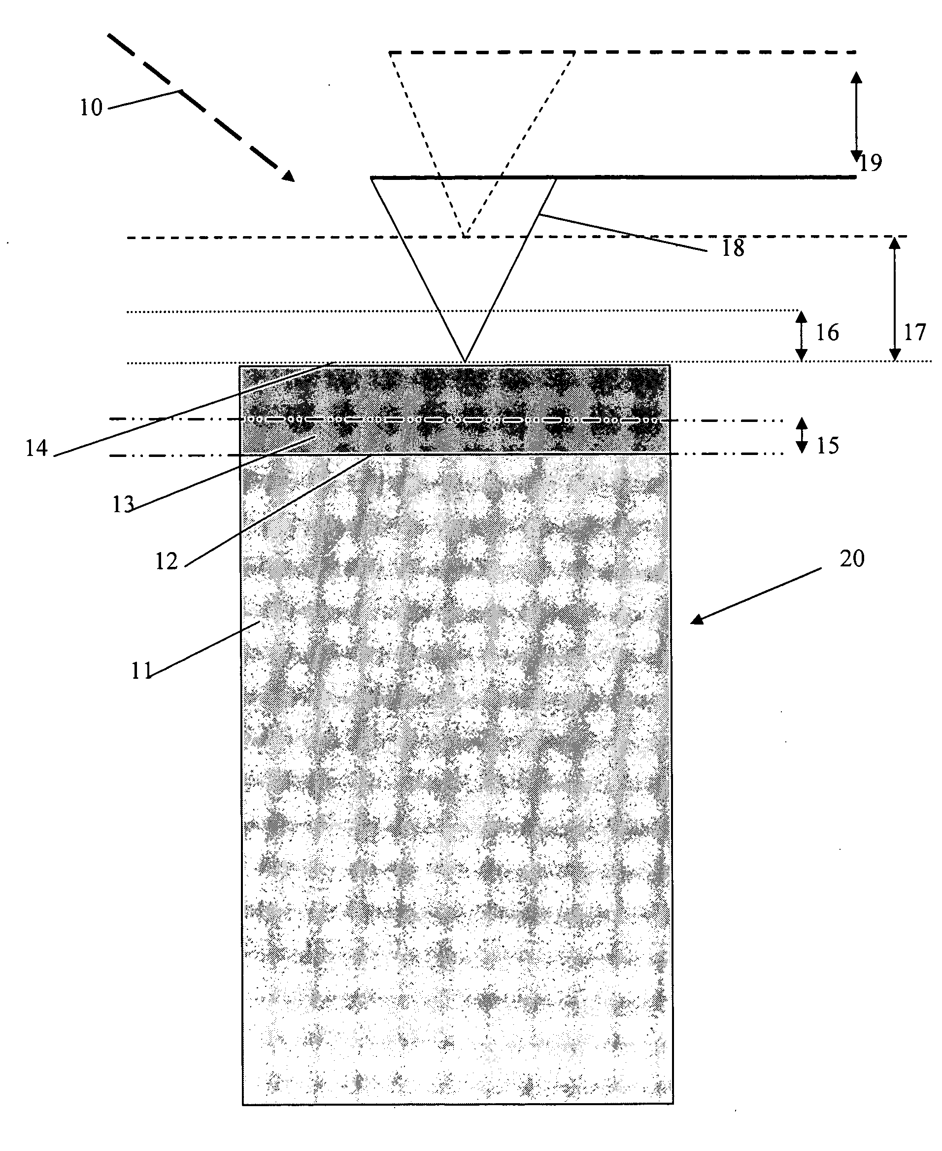
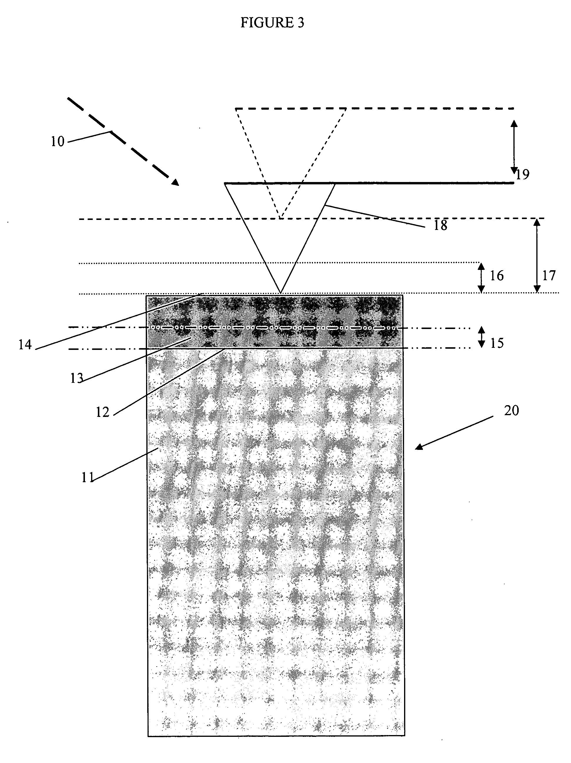
[0052] Probe 18 is heated with measured amplitude for the temperature modulation of 1° C. at a high modulation frequency at which the thermal diffusion length of the thermal wave is of the order of 0.1 units. The thermal wave does not penetrate much beyond top layer 13 and so the total height increase 17 and the apparent thermal diffusivity is mainly representative of the properties of top layer 13. A second measurement is performed using the heated probe 18 at the same amplitude of temperature modulation at a low frequency at which the thermal diffusion length is of the order of 1 unit. The thermal properties measured are representative of both bottom layer 11 and top layer 13, but mainly representative of the bottom layer 11 because it represents the majority of the material probed by the wave. In the simple case we are considering in this example, the thermal properties of bottom layer 11 and top layer 13 are the same and so the coefficient of thermal expansion and apparent therm...

example 2

[0053] The sample is illuminated by a photothermal radiation 1 of a wavelength that is absorbed by the bottom layer 11 but not the top layer 13 with an intensity that is modulated at the high and low frequencies. The intensity of the radiation 1 is adjusted so that a measured temperature modulation with amplitude of 1° C. is achieved. At the high frequency, the amplitude of the temperature expansion is greater than that observed in example 1, because the amplitude of the temperature modulation in bottom layer 11 required to achieve the 1° C. measured amplitude at the surface is greater than 1° C. because the wave is attenuated by top layer 13 which acts as an insulator. This greater than 1° C. amplitude tends to apply throughout the bottom layer 11 and also means that the measured thermal expansion is larger than in example 1. At the lower frequency, the thermal expansion is similar to that observed in example 1 because the top layer 13 has a much lesser attenuation effect at lower ...

example 3

[0054] The sample is illuminated by a photothermal radiation 1 of a wavelength that is absorbed by the top layer 13 but not by the bottom layer 11. The photothermal radiation is modulated at high and low frequencies. The intensity of the radiation is adjusted so that a measured temperature modulation with amplitude of 1° C. is achieved. At the high frequency, the amplitude of the temperature expansion is be similar to that observed in example 1. At the lower frequency the amplitude of the thermal expansion is similar to that observed in example 1.

[0055] Note that in example 2 at the high frequency, without the data from example 1, the data from example 2 cannot be interpreted easily. We simply observe an expansion and have nothing with which to compare it. With the data from example 1, that provides for a method of estimating the coefficient of thermal expansion, it is concluded that the absorbing layer must be the bottom layer 11. This very simple example illustrates two things:

[...


PUM

PropertyMeasurementUnit
wavelengthaaaaaaaaaa
temperatureaaaaaaaaaa

Abstract

A method and a system for generating a high spatial resolution multi-dimensional image representing the chemical composition of a sample. Highly localized IR light is used to cause the heating and thermal expansion of the sample. Modulating this IR light will cause this effect to take place at various depths of the material. The method and system of the present invention are used to generate a chemical profile of the sample using a combination of: (i) measurements of the thermal expansion and temperature change caused by absorbing IR radiation together; and (ii) measurements of the thermal expansion properties and thermal properties (such as thermal diffusivity and conductivity) of sites on the surface of the sample and the material surrounding it.

Description

CROSS-REFERENCE TO RELATED APPLICATIONS [0001] The present invention claims the benefit of U.S. Provisional Patent Application Ser. No. 60 / 668,077, filed Apr. 5, 2005, entitled “Method And Apparatus for Localized Infrared Spectroscopic Microtomography Combined With Scanning Probe Microscopy,” and Ser. No. 60 / 688,904, filed Jun. 9, 2005, entitled “Method And Apparatus for Localized Infrared Spectroscopic Microtomography Using A Combination Of Thermal Expansion and Temperature Change Measurements.” The content of both of the above-mentioned application is incorporated by reference herein.BACKGROUND OF THE INVENTION [0002] Techniques for the photothermal characterization of solids and thin films are widely used, as is described by D. P. Almond and P. M. Patel, “Photothermal Science and Techniques”, Chapman and Hall (London and New York, 1996). Recently the value of adding spatial resolution to these techniques has become of high technical interest in the general area of electronic and ...

Claims


Application Information

Patent Timeline
Patent Type & Authority Applications(United States)
IPC IPC(8): G01K1/16
CPCB82Y35/00G01Q60/58G01Q30/02G01N25/4833
Inventor READING, MICHAEL
Owner ANASYS INSTR
Why Eureka
Try Eureka