Filter
- Summary
- Abstract
- Description
- Claims
- Application Information
AI Technical Summary
Benefits of technology
Problems solved by technology
Method used
Image
Examples
first embodiment
[0056]FIG. 3 is a circuit diagram of a filter device according to the present invention.
[0057] The present embodiment corresponds to the embodiment in the first aspect of the present invention. The alternate circuit is a three-phase induction motor 31. The power converter with the alternating current output is an inverter 32. The induction motor 31 is inverter driven by the inverter 32. In FIG. 3, a ground line lg of a frame of the induction motor 31 is also shown.
[0058] In order to ground the minus terminals at the direct current input side of the inverter 32, a capacitor CG and a resistor RG that are connected in parallel are provided. The capacitor CG operates as a capacitor grounding for a high frequency component, and the resistor RG operates as a resistor grounding for a low frequency component.
[0059] A direct current capacitor Cdc is provided to store power at the power source system side of the inverter 32.
[0060] The inverter 32 is connected to a diode rectifier 33 that r...
second embodiment
[0082] A filter device according to the present invention is explained next.
[0083]FIG. 6 is a circuit diagram of the filter device according to the second embodiment of the present invention. FIG. 7 is an equivalent circuit diagram of the filter device according to the second embodiment of the present invention, and shows an equivalent circuit in a carrier frequency area in a common mode shown in FIG. 6.
[0084] The present embodiment corresponds to the embodiment according to the first aspect of the present invention. In the first embodiment shown in FIG. 3, a normal mode filter configured by a parallel circuit of a normal mode choke (that is, an alternating current reactor) L and a resistor R is further connected in series between the inverter 32 and the common mode reactor, with a view to decreasing resonance in a megahertz area. Other circuit configurations are similar to those of the first embodiment.
[0085] Based on the same idea of the equivalent circuit explained in the first...
third embodiment
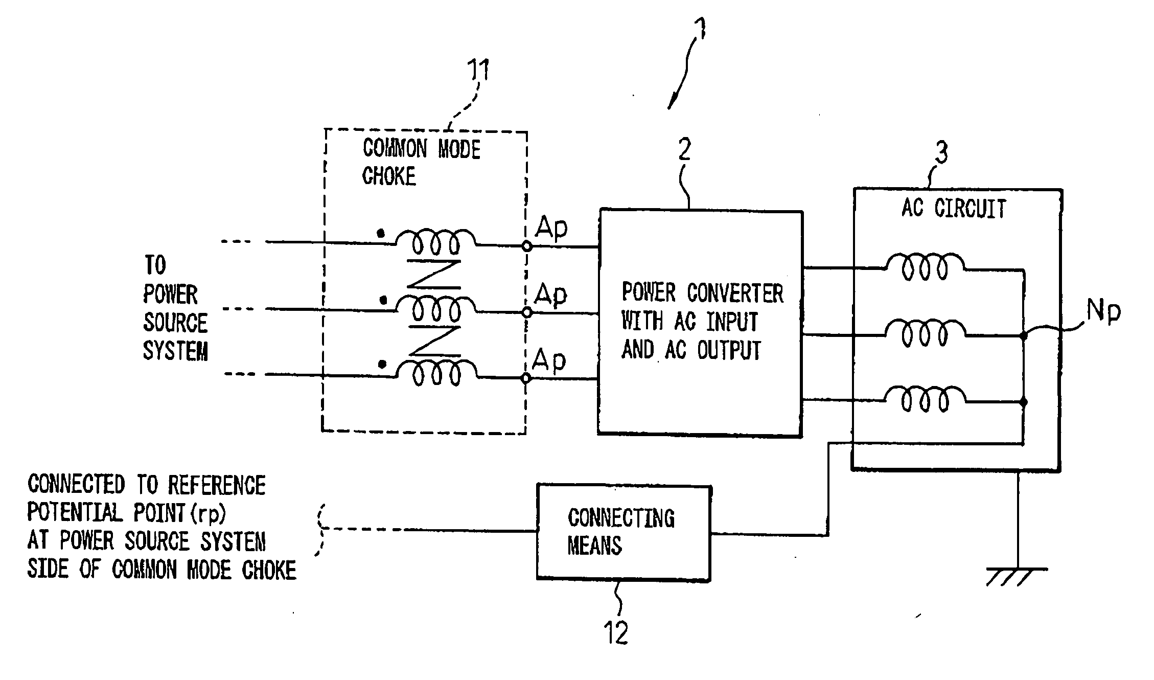
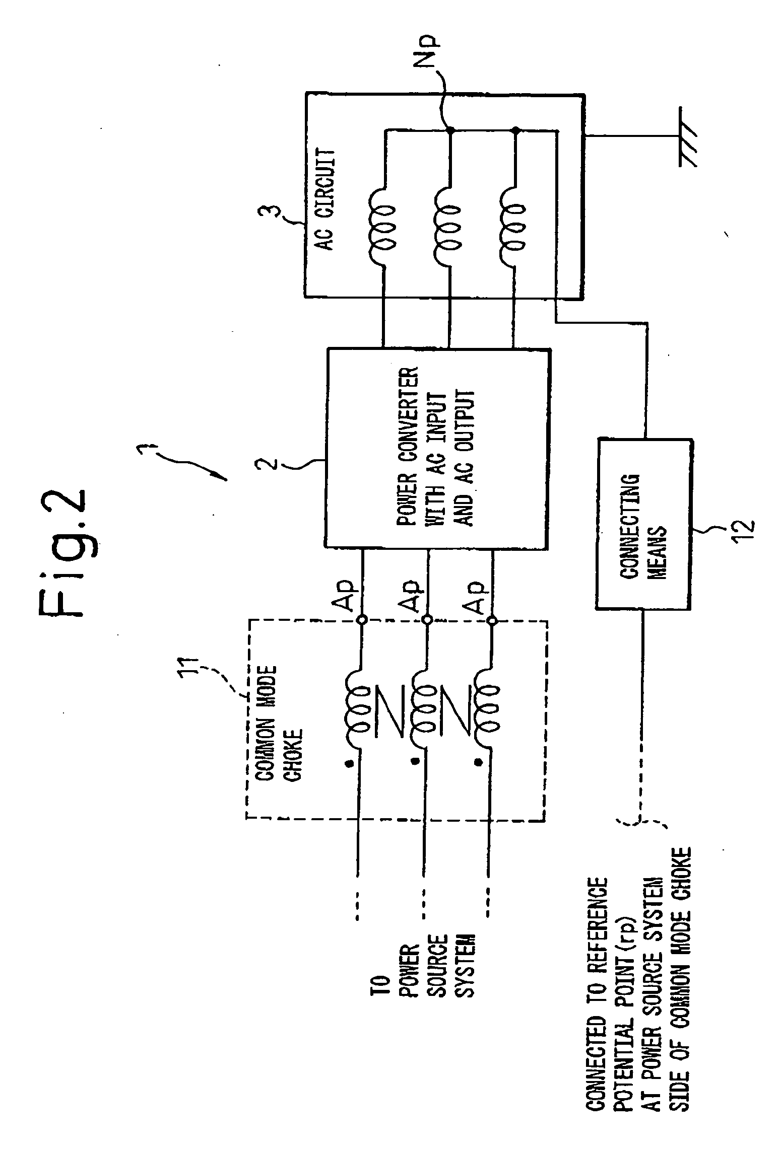
[0087] Next, a filter device that is applied when the power converter explained with reference to FIG. 1 is a converter with an alternating current input and an alternating current output is explained as the present invention.
[0088]FIG. 8 is a circuit diagram (part 1) of a filter device according to the third embodiment of the present invention, where a point having little voltage variation that becomes a reference potential point is not present at the input side of the power converter. FIG. 9 is a circuit diagram (part 2) of a filter device according to the third embodiment of the present invention, where a point having little voltage variation that becomes a reference potential point is present at the input side of the power converter.
[0089] The present embodiment corresponds to the embodiment according to the first aspect of the present invention. In the filter device 1, the power converter 2 shown in FIG. 8 and FIG. 9 is used as the converter with an alternating current input a...
PUM
 Abstract
Description
Claims
Application Information
 - R&D
- Intellectual Property
- Life Sciences
- Materials
- Tech Scout
- Unparalleled Data Quality
- Higher Quality Content
- 60% Fewer Hallucinations
Browse by: Latest US Patents, China's latest patents, Technical Efficacy Thesaurus, Application Domain, Technology Topic, Popular Technical Reports.
© 2025 PatSnap. All rights reserved.Legal|Privacy policy|Modern Slavery Act Transparency Statement|Sitemap|About US| Contact US: help@patsnap.com


